Menu
Physics Lesson 16.14.1 - LC Oscillations
Please provide a rating, it takes seconds and helps us to keep this resource free for all to use
Welcome to our Physics lesson on LC Oscillations, this is the first lesson of our suite of physics lessons covering the topic of Alternating Current. LC Circuits, you can find links to the other lessons within this tutorial and access additional physics learning resources below this lesson.
LC Oscillations
In the previous tutorials, we have discussed about the basic features of the electric and magnetic field, and methods how energy is stored in capacitors and inductors. Now, we will explore the methods, in which the energy stored in one place of the circuit can be transferred to another place in order to do any work. This is true for the energy transfer between different circuits as well. For example, the energy produced at a power plant is transferred through the mains electricity at our homes to run electric devices. Now, we will discuss how this is made possible through the energy transfer methods.
The current produced by cells and batteries is known as direct current (DC), as discussed in tutorial 16.2. This is because it is obtained through direct contact between battery and the conducting wire. However, most of energy in use today is transferred not as DC but rather, as alternating current (AC), which is a kind of electromagnetic oscillation propagating through the conductor in a sinusoidal way. Such oscillations are made possible through the induced current, which take place in LC circuits with inductance L and capacitance C.
So far, we have discussed about RC circuits, in which a capacitor is charged through a resistor and RL circuits, in which some of the energy produced by the source is stored in the magnetic field of an inductor. In both these kind of circuits, the current is not built immediately in the circuit but quantities such as current, charge or potential difference increase or decrease in an exponential fashion according a certain scale, represented through the time constant τ (τC for RC and τL for RL circuits).
LC circuits are different in this regard, i.e. the current and potential difference does not increase or decrease exponentially but in a sinusoidal fashion instead. The behavior of electric-related quantities here, is similar to all kinds of waves (especially electromagnetic ones) discussed in Sections 10 and 11 ("Simple Harmonic Motion" and "Waves"). The oscillations produced in the capacitor (resulting in the change of capacitor's electric field|) and in the inductor (resulting in the change in the inductor's magnetic field) are known as electromagnetic oscillations. Therefore, the energy is a LC circuit is always the sum of electric and magnetic energy stored in the capacitor and inductor respectively, i.e.
or
This situation is analogue to the mechanical energy stored in oscillating springs discussed in Section 5, which represents the sum of kinetic and potential energy of the system. If the mechanical energy is conserved (when no external factors interfere in the event), the kinetic energy is converted into potential and vice-versa; however, their sum (mechanical energy) is always constant.
We know from previous tutorials that a capacitor is charged and discharged in equal intervals (periods). When the capacitor is near the maximum value of charge it can store (near the full capacitance), the charge is built more slowly in it. This is analogue to when an object thrown upwards is near the highest position or when an oscillating spring is near the maximum deformation. When the capacitor is fully charged, the inductor does not store any energy in its magnetic field. As a result, the above equation becomes
On the other hand, when the capacitor is discharged, the entire energy of the circuit is stored in the magnetic field of the inductor. Hence, the equation representing the total energy in the circuit becomes
The inductor shows some resistance to the current flowing through it (from Lentz Law). Therefore, any change in the energy stored in the magnetic field of the inductor takes some time (period). Hence, any switch between the maximum and minimum values of energy stored in the capacitor or inductor occur in a periodical (and sinusoidal) fashion.
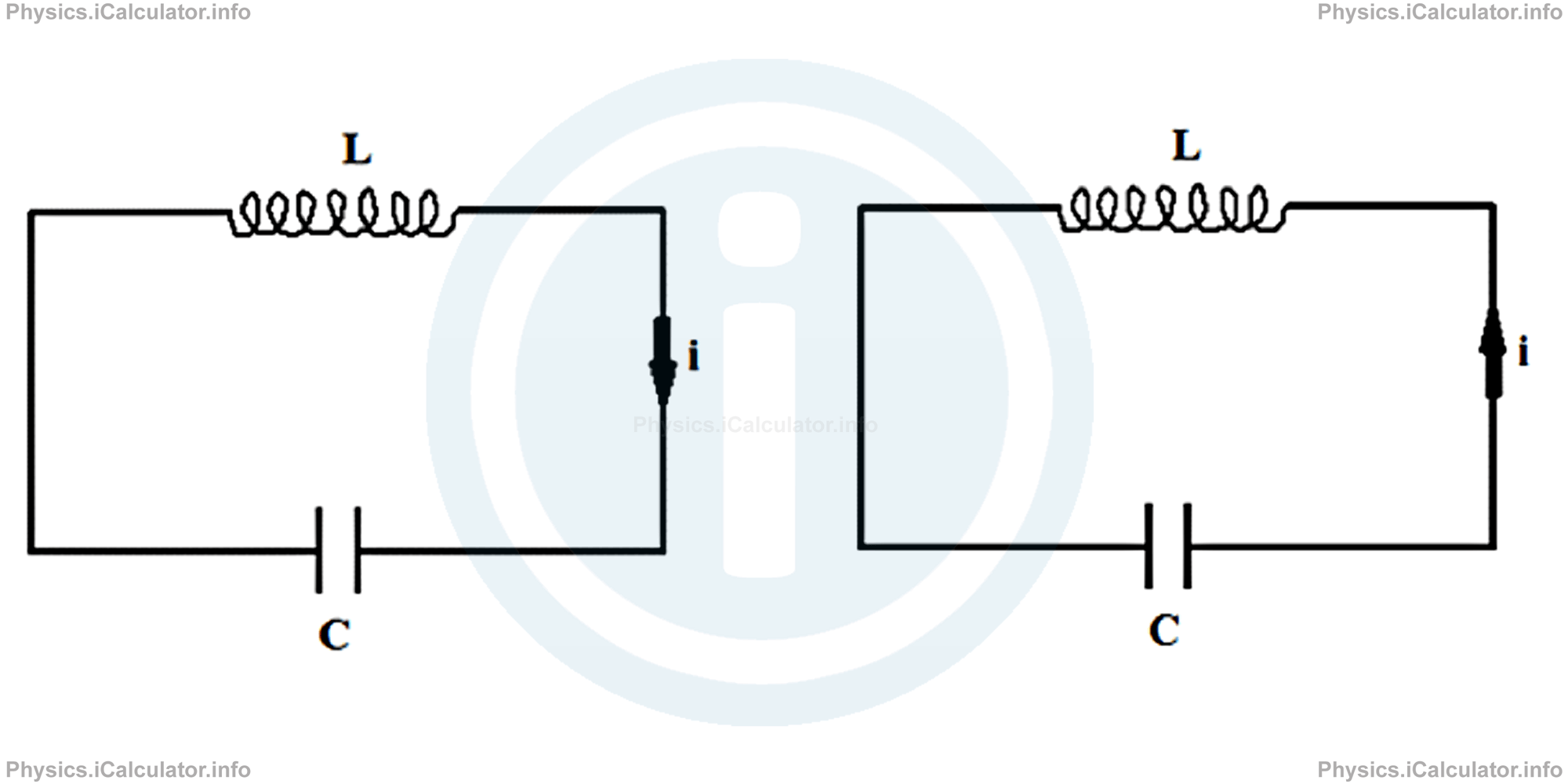
There is no direct source in such circuits, so we cannot assign a positive or negative direction to the current flow. As a result, the plates of capacitor are charged oppositely in equal time intervals. Look at the figure below.
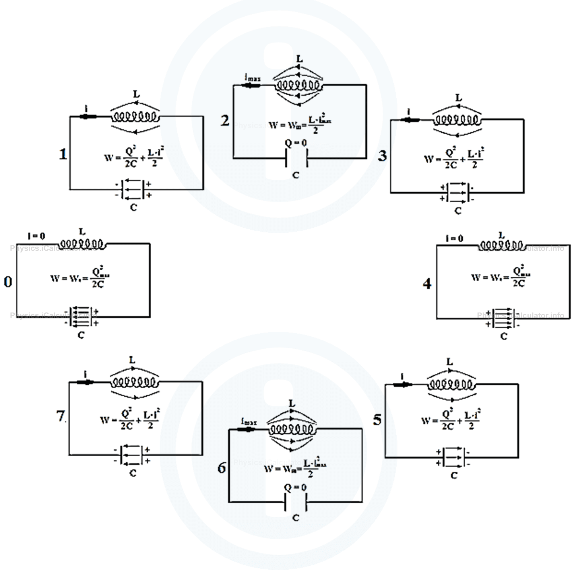
In the stage 0, there is no current flowing in the circuit; this means no energy is stored in the magnetic field of inductor. The capacitor is fully charged, and all the energy of the system is only electric due to the charge stored in the capacitor plates.
In the stage 1, the capacitor is discharging; some current is flowing throughout the circuit and therefore, a part of the total energy is stored in the magnetic field of the inductor. On the other hand, the electric energy stored in the capacitor is decreasing.
In the stage 2, the capacitor is fully discharged and all the energy of the system is stored in the magnetic field of inductor. This means the energy in the system is entirely magnetic. In addition, the current flowing through the circuit in this stage has the maximum value.
In the stage 3, the capacitor's plates are charging at the opposite signs to the stage 2 (due to the inertia of current, i.e. the charges are accumulating in the opposite plates of the capacitor in respect to the stage 1). As for the current, its value is decreasing, so the energy stored in the magnetic field is less than in the stage 2.
In the stage 4, the capacitor is again fully charged and no current is flowing through the circuit. Therefore, all energy of the system is stored in the capacitor plates in the form of electric energy. In a certain sense, this stage is similar to the initial one (stage 0) except the direction of the magnetic field between the plates of capacitor, which is opposite to that in the stage 0.
In the stage 5, the capacitor is discharging and the current in the circuit is increasing. This situation is similar to stage 1, except the direction of current and electric field between the capacitor plates is opposite to those in stage 1.
The stage 6 is similar to 2. All the energy of system is due to the energy stored in the magnetic field of inductor; the capacitor has no charge stored in its plates. The current is flowing at maximum rate in the circuit. However, the direction of current is opposite to that in stage 2.
In the stage 7, the current in the circuit is decreasing and the charges are accumulating at the capacitor plates at opposite direction to stage 4. The energy in the system is the sum of electric and magnetic ones.
Then, the process start from the beginning, i.e. if we included in the figure an eighth stage, it would be identical to the stage 0. This means the process is periodical.
As you see, these eight situations represent a whole cycle, in which the current switches between zero and imax. In addition, the current changes direction during its flow through the circuit. The same thing can be said for the magnetic field of the inductor as well. You can see from the direction of magnetic field lines that the poles of the electromagnet obtained by means of the current flow through the inductor. Since the current changes direction, the magnetic field lines change direction as well.
Remark! In the above analysis, we have neglected the heating effect of the conducting wire. In fact, the maximum potential energy stored in the magnetic field of inductor is not equal to the maximum electric field stored in the capacitor because some of the energy of capacitor turns into heat energy of wire. Therefore, we can write
Obviously, the equality sign is used only when we neglect the resistance of conducting wire of the circuit.
The graph below shows the relationship between the values of electric and magnetic energy stored in the capacitor and inductor respectively at any instant, not only in the eight stages discussed above. (The resistance of conductor is considered as the two energies are not equal when they are at maximum). 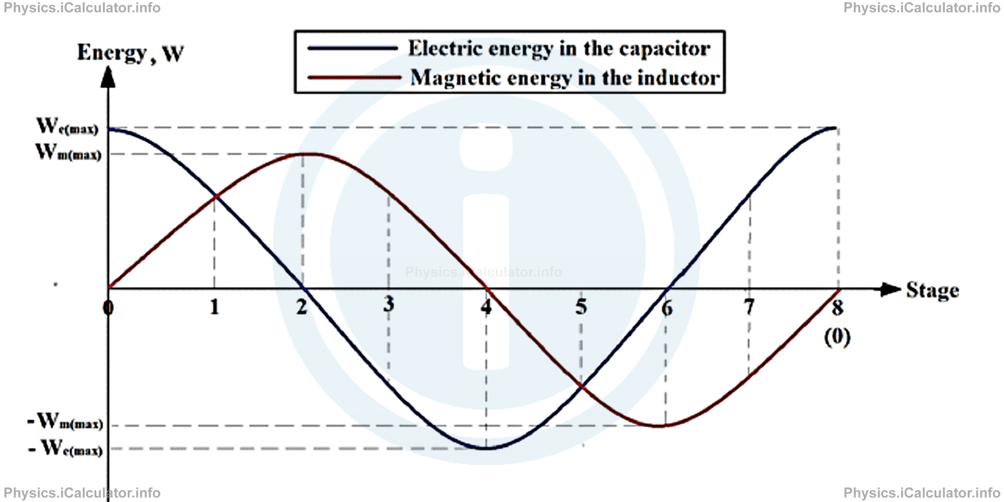
Both graphs are sinusoidal. This means the corresponding graphs for the current I flowing through the inductor and for the potential difference ΔV between the plates of capacitor are sinusoidal as well. Since by definition current is the amount of charge in the unit time and giving that the circuit has a certain resistance (and therefore a potential difference ΔVR = i ∙ R between the terminals due to this resistance), we conclude that all the four above quantities - the current i flowing in the circuit, the potential difference ΔVC between the capacitor plates, the charge Q stored in the capacitor plates, and the potential difference ΔVR due to the resistance of the circuit - are all sinusoidal.
As stated earlier, the graph will not continue to exist in the actual shape infinitely; the initial energy in the circuit will be lower than before after each cycle as some of this energy converts to heat due to the resistance in the circuit. This means the amplitudes (the vertical displacements of the graph in respect to the horizontal axis) will be lower and lower until both graphs become linear and converge at the horizontal axis. Therefore, a sustainable source is required to keep the values of the four above quantities repeat themselves for a long time.
Example 1
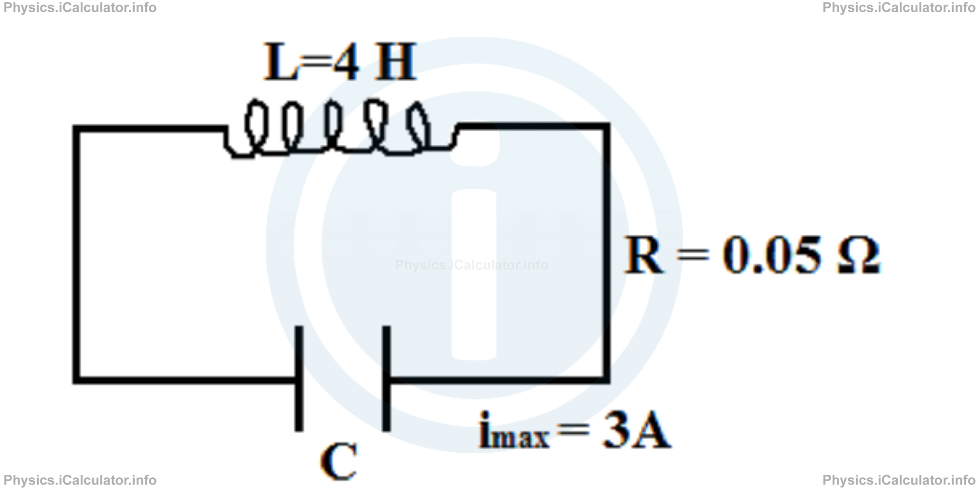
The maximum current flowing through a LC circuit is 3A. The resistance of the circuit is 0.05 Ω while the time needed to the current to complete a whole cycle is 0.02 s. The inductance of the solenoid is 4H. From these data, calculate
- The total energy stored in the circuit at the beginning of the process.
- The initial potential difference across the capacitor plates if it stores 4μC of charge at this instant
- The maximum charge stored in the capacitor plates after 5 cycles
- The number of cycles after which the energy remained in the system will be half of the initial energy.
Hint! We will see later that the average value of current flowing in AC circuits is calculated by
Solution 1
- The maximum initial energy of the system is calculated by finding the maximum energy stored in the inductor during the first cycle. Thus, W0(max) = L ∙ imax2/2
= (4 H) ∙ (3 A)2/2
= 18 J - The maximum energy stored in the magnetic field of inductor during the first cycle is equal to electric energy stored in the inductor during the same cycle. Thus, since W0(max) = (Q20)/2Cwe obtain for the capacitance of capacitor:C = Q20/2W0(max)
= 4 × 10⁻⁶ C)2/2 ∙ (18 J)
= 4.44 × 10⁻¹³ F - Based on the Joule's Law, the total energy in the circuit decreases by a value of ∆W = < i >2 ∙ R ∙ ∆tafter each cycle in respect to the previous value. Thus, the decrease in energy of the system after 5 cycles (N = 5) is∆Wn = N ∙ < i >2 ∙ R ∙ ∆tTherefore, the energy remained in the system after 5 cycles is
= 5 ∙ (imax/√2)2 ∙ R ∙ ∆t
= 5 ∙ (3A/√2)2 ∙ (0.05Ω) ∙ (0.02 s)
= 0.0225 JW5 = W0(max) - ∆W5
= 18 J - 0.0225 J
= 17.9775 J - Now, we use the relation Wn = W0(max) -N ∙ ∆W1where N is the number of cycles and ΔW1 = < i > ∙ R is the decrease in the total energy in the system after each cycle. It represents the amount of energy converted into heat during each cycle due to the resistance of the circuit. Thus, since WN = 1/2 Wmax = 9J, we obtain9 = 18-N ∙ (3A/√2)2 ∙ (0.05Ω) ∙ (0.02 s)
N ∙ (0.0045 J) = 18J - 9J = 9J
N = 9J/0.0045 J
= 2000 cycles
You have reached the end of Physics lesson 16.14.1 LC Oscillations. There are 5 lessons in this physics tutorial covering Alternating Current. LC Circuits, you can access all the lessons from this tutorial below.
More Alternating Current. LC Circuits Lessons and Learning Resources
Whats next?
Enjoy the "LC Oscillations" physics lesson? People who liked the "Alternating Current. LC Circuits lesson found the following resources useful:
- Lc Oscillations Feedback. Helps other - Leave a rating for this lc oscillations (see below)
- Magnetism Physics tutorial: Alternating Current. LC Circuits. Read the Alternating Current. LC Circuits physics tutorial and build your physics knowledge of Magnetism
- Magnetism Revision Notes: Alternating Current. LC Circuits. Print the notes so you can revise the key points covered in the physics tutorial for Alternating Current. LC Circuits
- Magnetism Practice Questions: Alternating Current. LC Circuits. Test and improve your knowledge of Alternating Current. LC Circuits with example questins and answers
- Check your calculations for Magnetism questions with our excellent Magnetism calculators which contain full equations and calculations clearly displayed line by line. See the Magnetism Calculators by iCalculator™ below.
- Continuing learning magnetism - read our next physics tutorial: Introduction to RLC Circuits
Help others Learning Physics just like you
Please provide a rating, it takes seconds and helps us to keep this resource free for all to use
We hope you found this Physics lesson "Alternating Current. LC Circuits" useful. If you did it would be great if you could spare the time to rate this physics lesson (simply click on the number of stars that match your assessment of this physics learning aide) and/or share on social media, this helps us identify popular tutorials and calculators and expand our free learning resources to support our users around the world have free access to expand their knowledge of physics and other disciplines.
Magnetism Calculators by iCalculator™
- Angular Frequency Of Oscillations In Rlc Circuit Calculator
- Calculating Magnetic Field Using The Amperes Law
- Capacitive Reactance Calculator
- Current In A Rl Circuit Calculator
- Displacement Current Calculator
- Electric Charge Stored In The Capacitor Of A Rlc Circuit In Damped Oscillations Calculator
- Electric Power In A Ac Circuit Calculator
- Energy Decay As A Function Of Time In Damped Oscillations Calculator
- Energy Density Of Magnetic Field Calculator
- Energy In A Lc Circuit Calculator
- Faradays Law Calculator
- Frequency Of Oscillations In A Lc Circuit Calculator
- Impedance Calculator
- Induced Emf As A Motional Emf Calculator
- Inductive Reactance Calculator
- Lorentz Force Calculator
- Magnetic Dipole Moment Calculator
- Magnetic Field At Centre Of A Current Carrying Loop Calculator
- Magnetic Field In Terms Of Electric Field Change Calculator
- Magnetic Field Inside A Long Stretched Current Carrying Wire Calculator
- Magnetic Field Inside A Solenoid Calculator
- Magnetic Field Inside A Toroid Calculator
- Magnetic Field Produced Around A Long Current Carrying Wire
- Magnetic Flux Calculator
- Magnetic Force Acting On A Moving Charge Inside A Uniform Magnetic Field Calculator
- Magnetic Force Between Two Parallel Current Carrying Wires Calculator
- Magnetic Potential Energy Stored In An Inductor Calculator
- Output Current In A Transformer Calculator
- Phase Constant In A Rlc Circuit Calculator
- Power Factor In A Rlc Circuit Calculator
- Power Induced On A Metal Bar Moving Inside A Magnetic Field Due To An Applied Force Calculator
- Radius Of Trajectory And Period Of A Charge Moving Inside A Uniform Magnetic Field Calculator
- Self Induced Emf Calculator
- Self Inductance Calculator
- Torque Produced By A Rectangular Coil Inside A Uniform Magnetic Field Calculator
- Work Done On A Magnetic Dipole Calculator