Menu
Physics Lesson 15.5.4 - Solving Complex Circuits using the Kirchhoff Laws
Please provide a rating, it takes seconds and helps us to keep this resource free for all to use
Welcome to our Physics lesson on Solving Complex Circuits using the Kirchhoff Laws, this is the fourth lesson of our suite of physics lessons covering the topic of Kirchhoff Laws, you can find links to the other lessons within this tutorial and access additional physics learning resources below this lesson.
Solving Complex Circuits using the Kirchhoff Laws
Complex circuits that cannot be solved using Ohm's Law, require a different strategy, which involves the application of Kirchhoff Laws. Each law generates a linear equation. As a result, a number of linear equation is obtained. This number depends on the number of principal nodes and loops in the circuit. There are equations involving the current law at each principal node and other equations involving the voltage law in each loop of the circuit. In general, the equations of currents in the principal nodes are equivalent, so usually we consider only one equation for currents.
As for voltages, we use a different equation for each loop. As a result, we obtain a system of linear equations that is solved using any of the three known methods of solving systems of linear equations (elimination, substitution or graph method).
The procedure for solving a circuit using the Kirchhoff Laws is as follows:
Step 1 - Make sure to write a clear circuit diagram on which you can label all known and unknown resistances, electromotive forces, and currents. If you are not sure about the direction of any current, you must anyway assign it a direction. This is necessary for determining the signs of potential differences. If you assign the direction of current incorrectly, it will result in a negative value. This is not a problem; you just realize that current is flowing in the opposite direction.
Step 2 - Apply the current rule in each principal node (junction). Every time you must get different equations, otherwise the equations are redundant, i.e. they repeat themselves. If there are only two opposite principal nodes in the circuit, the equation of currents is written only once, as the other is redundant.
Step 3 - Apply the loop rule for as many loops as needed (not necessary for each loop) to solve for the unknowns in the problem. (There must be as many independent equations as unknowns.) To apply the loop rule, you must choose a direction to go around the loop. Then carefully and consistently determine the signs of the potential differences and electromotive forces for each element.
Step 4 - Solve the system of linear equations. You need to express one of the currents in terms of the other two and substitute it in the system of equations involving voltages and electromotive forces.
Step 5 - Check the results you obtained for the currents substituting them in the equation of the current law. Also, make sure any resistance is not negative or it does not have an unreasonable value (very large or very small).
Now, let's consider a couple of examples where the Kirchhoff Laws are used.
Example 1
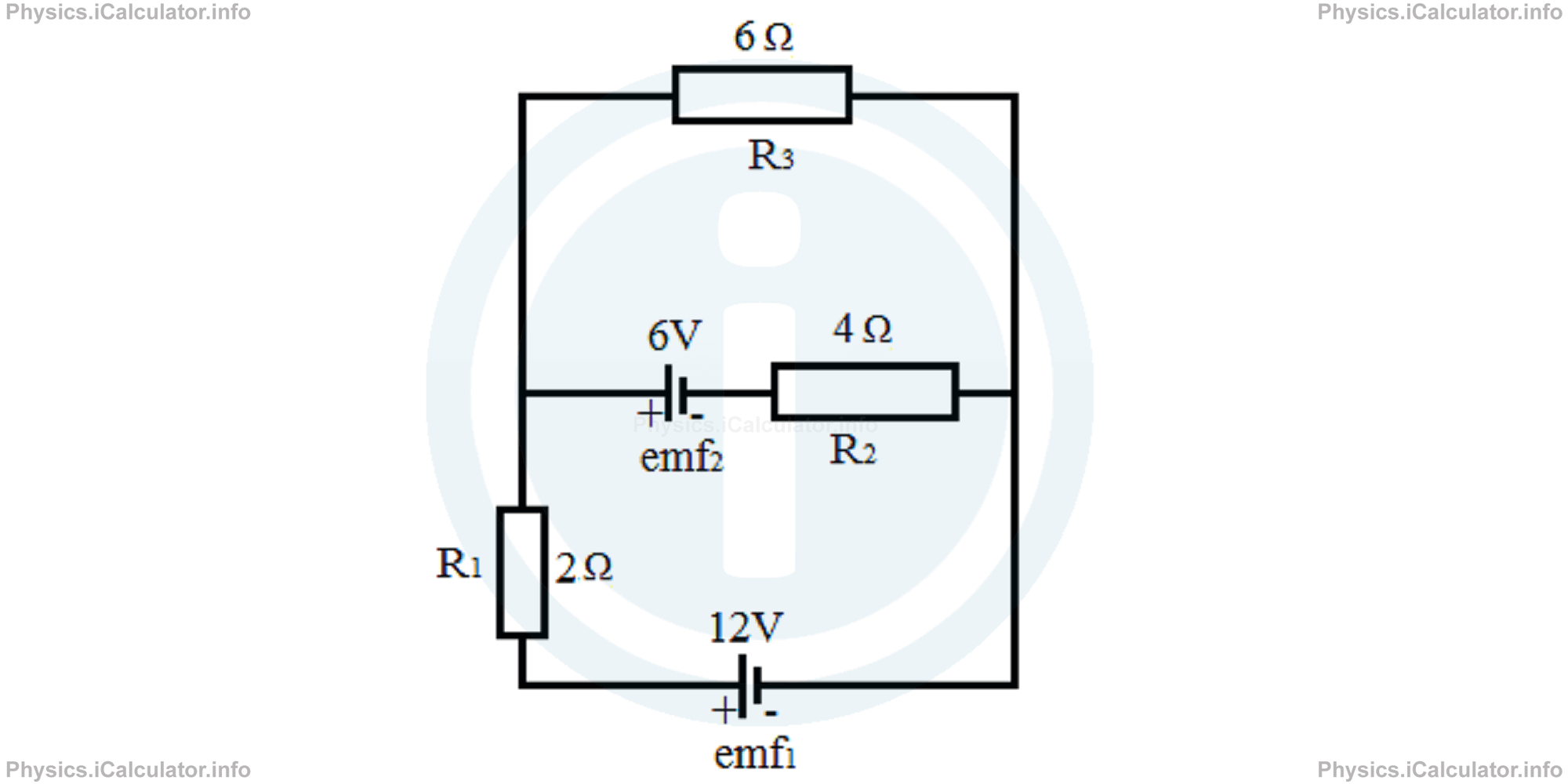
Calculate the currents flowing in all parts of the circuit below.
Solution 1
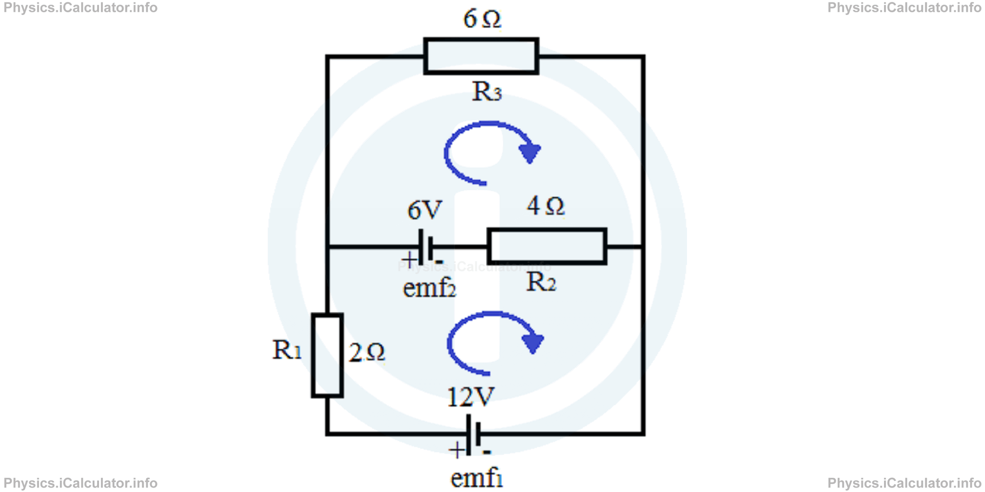
First, let's assign a positive direction to the current flow. It is better to choose the direction determined by the larger battery (here it is easy as both batteries produce a clockwise current) as the direction of current flow in the entire circuit.
Now, let's determine the equation for currents based on the First Kirchhoff Law (the law of currents). We have two principal nodes aside emf2 and R2. They are opposite nodes, so they produce the same (redundant) equations. Therefore, we consider only one node (for example the left one, i.e. the node A) to determine the equation of currents.
There are two currents entering the node (I1 produced by emf1 and I2 produced by emf2). Therefore, the current I3 flowing through the resistor R3 will leave the node A as shown in the figure.
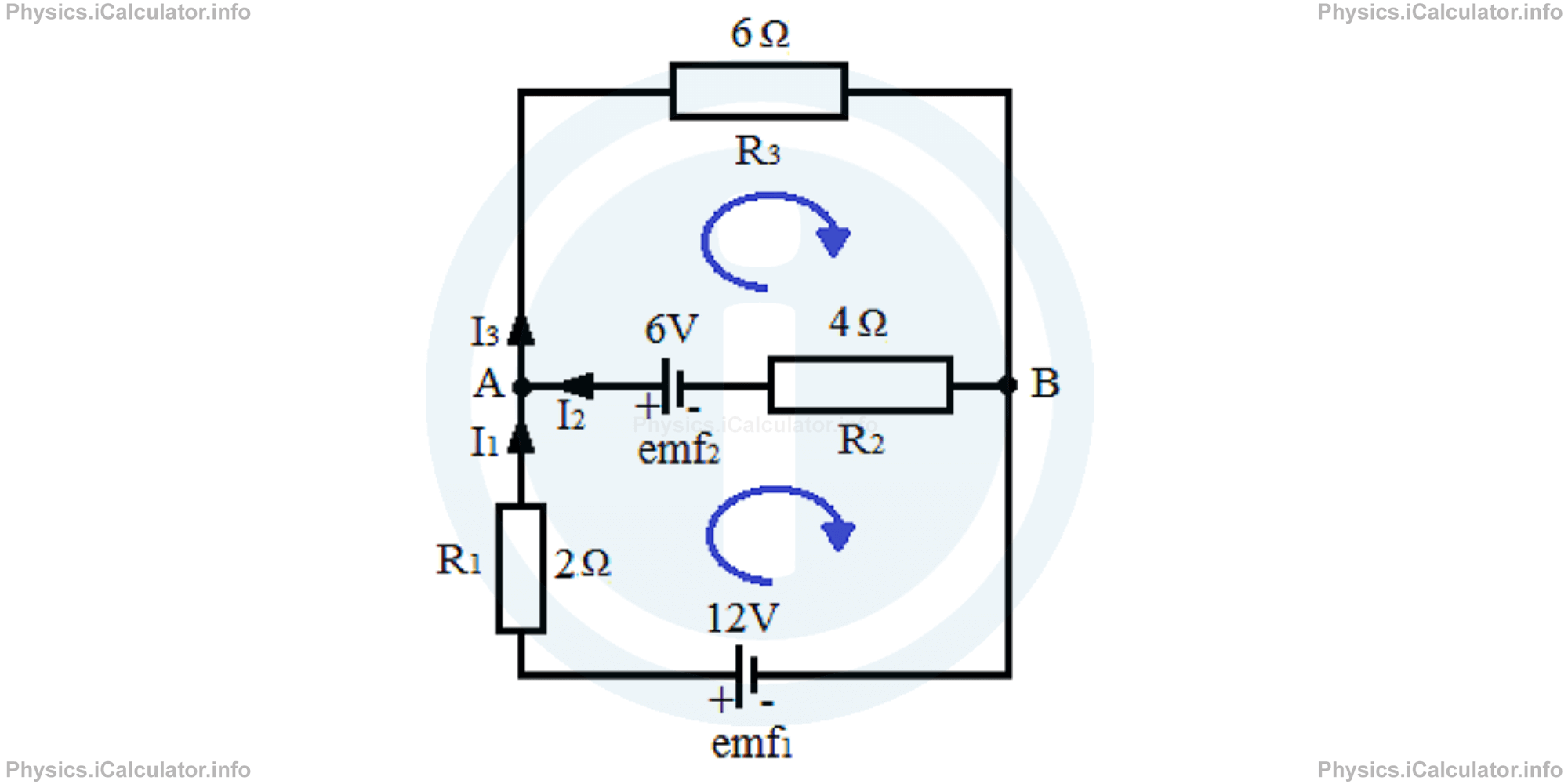
Hence, the equation of currents will be
Now, let's determine the equations for the voltages flowing in each loop (we consider two loops: one that is determined from the lower branch (emf1 ― R1 ― node A ― emf2 ― R2 ― node B - emf1) and the other from the higher branch (emf2 ― node A ― R3 ― node B ― R2 ― emf2). These equations form a system of linear equations shown below:
(The electromotive force emf2 in the second source and the potential difference in the second resistor ΔV2 = I2 ∙ R2 are taken as negative for the lower loop as they are in the anticlockwise direction if we take this loop as a reference, despite they have a positive direction if considering the upper loop. This situation is similar to when we raise the left hand in front of a plane mirror and it seems like our image in the mirror raises the right hand.)
Substituting the values (let's skip the units for now), we obtain
6 = I1 ∙ 2 - I2 ∙ 46 = I2 ∙ 4 + I3 ∙ 6
Since all values are even, we can simplify every term by 2, i.e.
This system contains three variables and two equations. Since the number of equations is smaller than that of variables, we must reduce the number of variables, i.e. we must write one of currents in terms of the other two. It is better to express the current I3 in terms of I1 and I2 in the second equation. Thus, we obtain
3 = I1 - I2 ∙ 23 = I2 ∙ 2 + I1 ∙ 3 + I2 ∙ 3
3 = I1 - I2 ∙ 23 = I1 ∙ 3 + I2 ∙ 5
Let's solve this system by the substitution method. Thus, from the first equation we have
I1 = 3 + I2 ∙ 2
Now, let's substitute this value of I1 in the second equation and then solve for I2.
3 = 9 + 6I2 + 5I2
-6 = 11I2
I2 = -6/11 A
The negative value means our assumption for the direction of current I2 was wrong. The current I2 flows in the other direction.
Substituting this value found for I2 in any of the equations, we obtain
= 3 - 12/11
= 33/11 - 12/11
= 21/11 A
From the currents law, we obtain for the current I3:
= 21/11 A + (-6/11) A
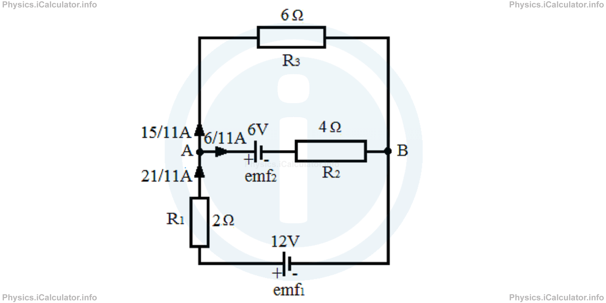
= 15/11 A
Thus, we must correct the direction of currents to fit the results. From the above values, we can conclude that only the current I1 enters the node A, the other two currents leave the node. The final situation is shown in the figure below.
Therefore, the equation for currents must have been written as
We could obtain the same result by taking as the first loop the long loop that includes the entire frame of the circuit. The second loop is the same as before. Taking again the same equation for the currents (I1 + I2 = I3), we write for voltages
12 = I1 ∙ 2 + I3 ∙ 66 = I2 ∙ 4 + I3 ∙ 6
Again, we simplify all terms by 2. Thus,
Substituting I1 with I2 + I3 we have
6 = I1 + I3 ∙ 33 = I3 ∙ 2-I1 ∙ 2 + I3 ∙ 3
6 = I1 + I3 ∙ 33 = -I1 ∙ 2 + I3 ∙ 5
Multiplying the first equation by 2 and adding it with the second equation, we obtain
15 = I3 ∙ 11
I3 = 15/11 A
Also,
66/11 = I1 + 45/11
I1 = 21/11 A
and
= 15/11 A - 21/11 A
= -6/11 A
In this way, we obtained the same results as when using the first method.
Now, let's see another example in which batteries produce currents in opposite directions.
Example 2
Calculate the currents flowing in the circuit shown in the figure.
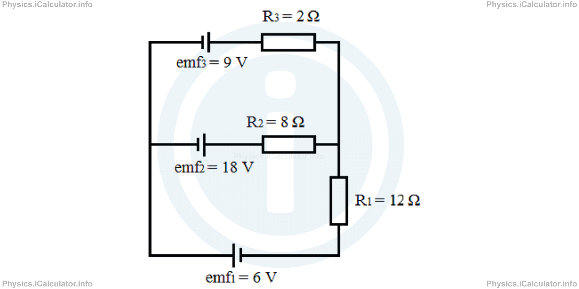
Solution 2
Let's consider the principal node on the right. Given the position of the poles of each battery, we assume as a possible direction of currents the equation below
The figure below shows the flowing direction of the above currents. Also, we can take again the clockwise direction as positive.
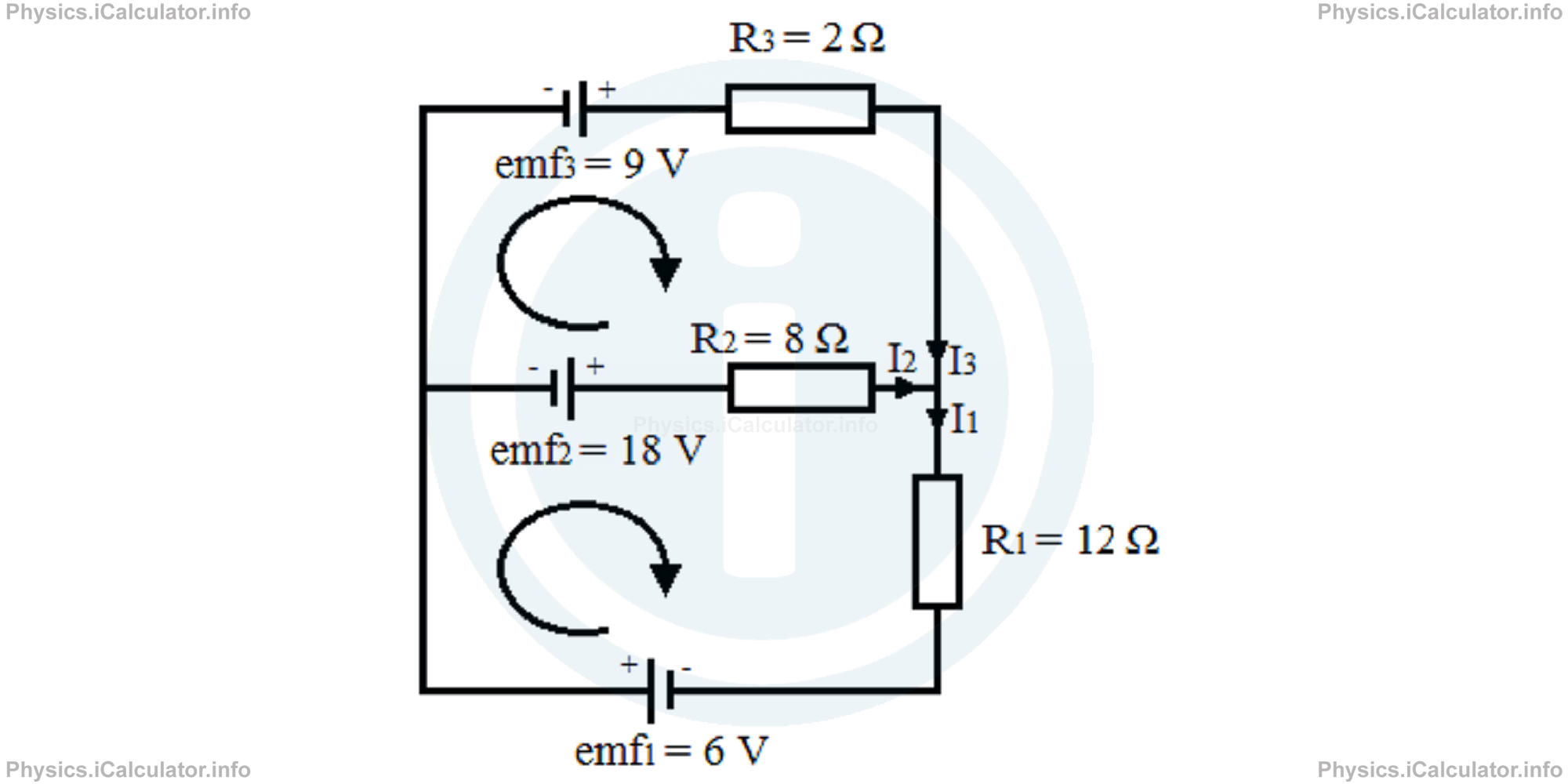
Let's take as loops the two halves of the circuit. Hence, we obtain the following system of linear equations based on the Kirchhoff Voltage Law:
6 + 18 = I1 ∙ 12 + I2 ∙ 8-18 + 9 = -I2 ∙ 8 + I3 ∙ 2
24 = I1 ∙ 12 + I2 ∙ 8-9 = -I2 ∙ 8 + I3 ∙ 2
Substituting I1 with I2 + I3 in the first equation, we obtain
24 = (I2 + I3 ) ∙ 12 + I2 ∙ 8-9 = -I2 ∙ 8 + I3 ∙ 2
24 = I2 ∙ 12 + I3 ∙ 12 + I2 ∙ 8-9 = -I2 ∙ 8 + I3 ∙ 2
24 = I2 ∙ 20 + I3 ∙ 12-9 = -I2 ∙ 8 + I3 ∙ 2
Let's multiply the second equation by -6 to eliminate I3 and then add the equations:
78 = 68 ∙ I2
I2 = 7868 A
=3934 A
Substituting this value in the first equation (after simplifying all terms by 4 to make the calculations easier), we obtain
6 = I2 ∙ 5 + I3 ∙ 3
6 = 39/34 ∙ 5 + I3 ∙ 3
204/34 = 195/34 + I3 ∙ 3
I3 ∙ 3 = 9/34
I3 = 3/34 A
Therefore, we obtain for I1:
= 39/34 A + 3/34 A
= 42/34 A
All results are reasonable and positive, so our initial assumption for current was true.
You have reached the end of Physics lesson 15.5.4 Solving Complex Circuits using the Kirchhoff Laws. There are 4 lessons in this physics tutorial covering Kirchhoff Laws, you can access all the lessons from this tutorial below.
More Kirchhoff Laws Lessons and Learning Resources
Whats next?
Enjoy the "Solving Complex Circuits using the Kirchhoff Laws" physics lesson? People who liked the "Kirchhoff Laws lesson found the following resources useful:
- Complex Circuits Feedback. Helps other - Leave a rating for this complex circuits (see below)
- Electrodynamics Physics tutorial: Kirchhoff Laws. Read the Kirchhoff Laws physics tutorial and build your physics knowledge of Electrodynamics
- Electrodynamics Revision Notes: Kirchhoff Laws. Print the notes so you can revise the key points covered in the physics tutorial for Kirchhoff Laws
- Electrodynamics Practice Questions: Kirchhoff Laws. Test and improve your knowledge of Kirchhoff Laws with example questins and answers
- Check your calculations for Electrodynamics questions with our excellent Electrodynamics calculators which contain full equations and calculations clearly displayed line by line. See the Electrodynamics Calculators by iCalculator™ below.
- Continuing learning electrodynamics - read our next physics tutorial: Electric Power and Efficiency
Help others Learning Physics just like you
Please provide a rating, it takes seconds and helps us to keep this resource free for all to use
We hope you found this Physics lesson "Kirchhoff Laws" useful. If you did it would be great if you could spare the time to rate this physics lesson (simply click on the number of stars that match your assessment of this physics learning aide) and/or share on social media, this helps us identify popular tutorials and calculators and expand our free learning resources to support our users around the world have free access to expand their knowledge of physics and other disciplines.
Electrodynamics Calculators by iCalculator™
- Amount Of Substance Obtained Through Electrolysis Calculator
- Charge Density Calculator
- Electric Charge Stored In A Rc Circuit Calculator
- Electric Field In Terms Of Gauss Law Calculator
- Electric Power And Efficiency Calculator
- Electron Drift Velocity Calculator
- Equivalent Resistance Calculator
- Force Produced By An Electric Source Calculator
- Joules Law Calculator
- Ohms Law Calculator
- Potential Difference In Rc Circuit Calculator
- Resistance Due To Temperature Calculator
- Resistance Of A Conducting Wire Calculator