Menu
Physics Lesson 16.16.2 - The Current Amplitude
Please provide a rating, it takes seconds and helps us to keep this resource free for all to use
Welcome to our Physics lesson on The Current Amplitude, this is the second lesson of our suite of physics lessons covering the topic of The Series RLC Circuit, you can find links to the other lessons within this tutorial and access additional physics learning resources below this lesson.
The Current Amplitude
First, let's express the current in a series RLC circuit through a phasor diagram like the one shown below.
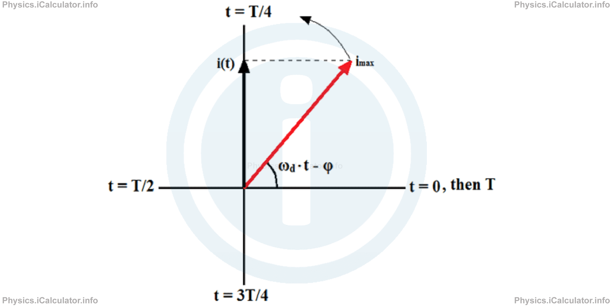
We can draw the three phasors of voltage for the above position of the current phasor. Thus, since current and voltage across the resistor are in phase, the phasor arrow of the resistive voltage will be collinear with that of current.
On the other hand, the current in the capacitor leads the voltage by π/2 (a quarter of a cycle, or rotation). Therefore, the capacitive voltage phasor is displaced by π/2 radians anticlockwise to the current phasor because capacitive voltage is quarter a cycle behind the current.
Finally, since the current is behind by π/2 to the voltage (it lags voltage by quarter of a cycle), the inductive voltage phasor is displaced by π/2 clockwise to the current phasor.
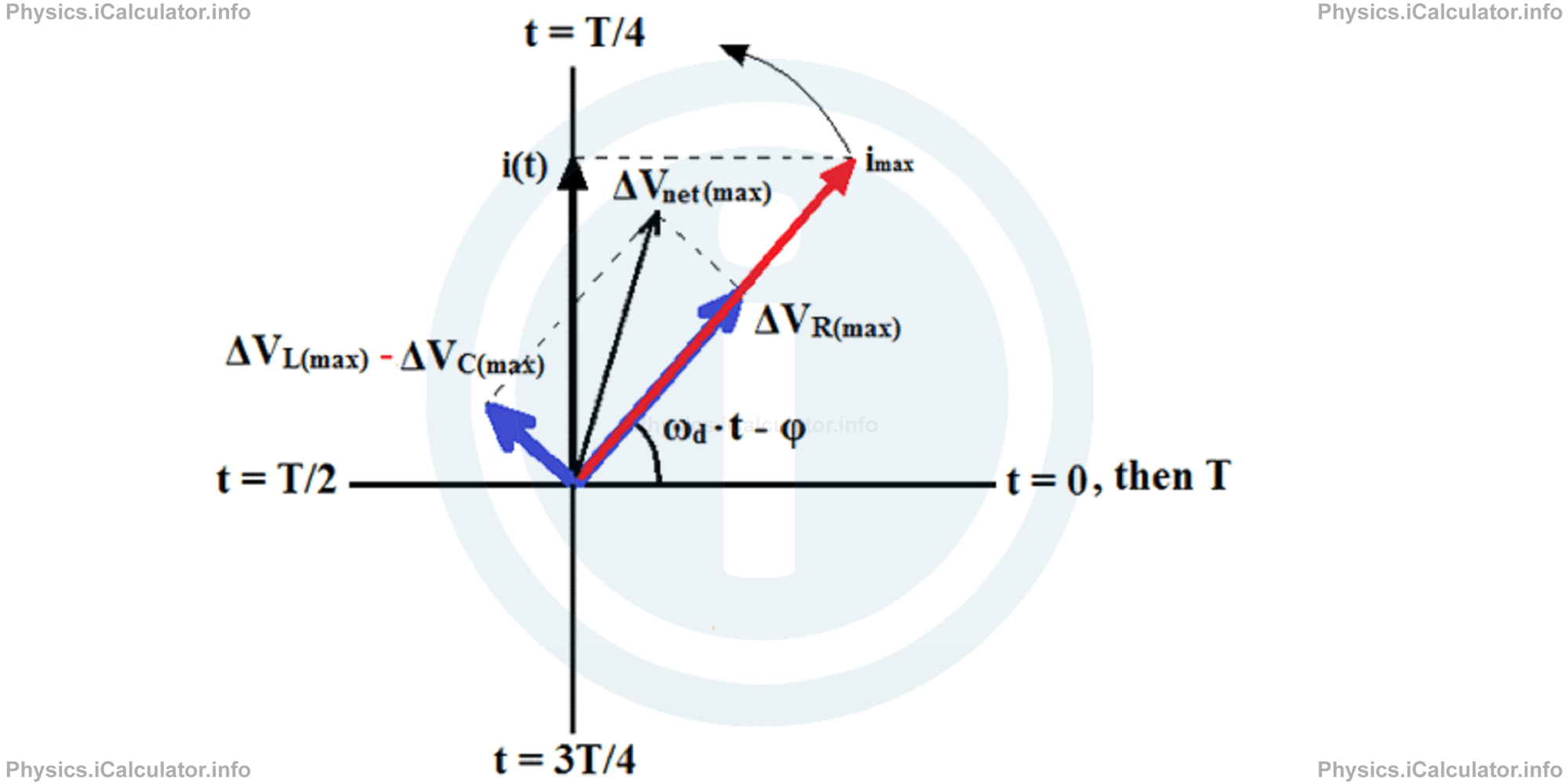
The following figure shows all four phasors discussed above.
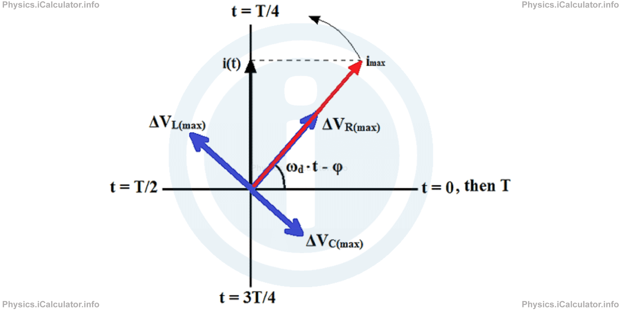
The projections of each voltage phasor in the vertical axis give the instantaneous values of the corresponding voltages. They are not shown in the diagram to avoid making it too much crowded.
Since ΔVC(max) and ΔVL(max) have opposite directions, it is better to subtract them, just as we do when subtracting two vectors. Then, we find the resultant of (ΔVL(max) - ΔVC(max)) and ΔVR(max), which represents the net maximum voltage Vnet(max) by applying the rules of vectors addition.
Giving that at any instant the phasors obey the rule
we obtain for the amplitudes of the above quantities (when phasors are taken as vectors):
Let's use the rules of vector addition to find the net maximum voltage in terms of the other three voltages. Using the notation (ΔVL(max) - ΔVC(max)) instead of their separate notation, we obtain for the net voltage:
The last equation is obtained by applying the Pythagorean Theorem. Using the Ohm's Law for each component, we obtain
where XL and XC are the inductive and capacitive reactances in the circuit respectively.
Rearranging the last equation for the maximum current, we obtain
The expression √R2 + (XL-Xc )2 is known as impedance Z of the RLC circuit for the given driving angular frequency ωd. It represents the total opposition a RLC circuit presents to current flow. The unit of impedance is Ohm, Ω. Hence, we have
Thus, we can write
If we substitute the reactances XL and XC with their corresponding expressions found in the previous tutorial, we obtain
Example 1
The voltage in the series RLC circuit shown in the figure oscillates according the expression ε(t) = 150 sin (120π ∙ t).
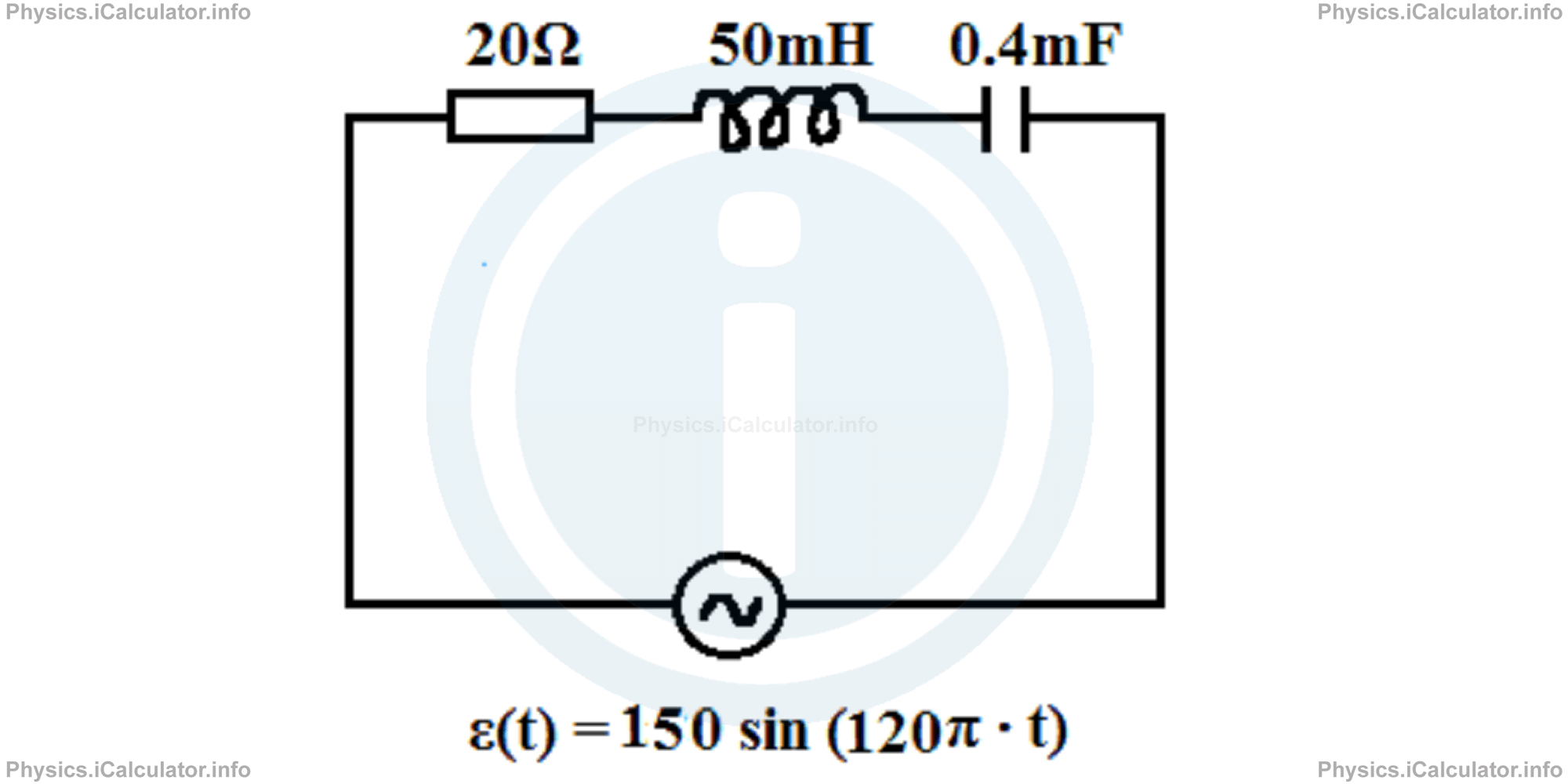
The values of resistance, inductance and capacitance of the corresponding circuit elements are 20Ω, 50mH and 0.4mF respectively. Calculate:
- The frequency in the circuit
- The impedance in the circuit
- The maximum current flowing in the circuit
Solution 1
- Since the equation of voltage in a RLC circuit has the form ε(t) = εmax ∙ sin(ωd ∙ t)It is clear that εmax = 150V and ωd = 120π rad/s. Also, we haveωd = 2 ∙ π ∙ f = 120π
2f = 120
f = 60Hz - From the equation of impedance Z, we have (giving that L = 50mH = 0.05 H and C = 0.4mF = 0.0004 F): Z = √R2 + (XL-Xc )2
= √R2 + (ωd ∙ L-1/ωd ∙ C)2
= √202 + (120 ∙ 0.05 - 1/120 ∙ 0.0004)2
= √202 + (6 - 20.8)2
= √202 + (-14.8)2
= √400 + 219
= √619
= 24.9Ω - The maximum current flowing through the circuit is given by: imax = εmax/Z
= 150 V/24.9Ω
= 6.02A
You have reached the end of Physics lesson 16.16.2 The Current Amplitude. There are 5 lessons in this physics tutorial covering The Series RLC Circuit, you can access all the lessons from this tutorial below.
More The Series RLC Circuit Lessons and Learning Resources
Whats next?
Enjoy the "The Current Amplitude" physics lesson? People who liked the "The Series RLC Circuit lesson found the following resources useful:
- Current Amplitude Feedback. Helps other - Leave a rating for this current amplitude (see below)
- Magnetism Physics tutorial: The Series RLC Circuit. Read the The Series RLC Circuit physics tutorial and build your physics knowledge of Magnetism
- Magnetism Revision Notes: The Series RLC Circuit. Print the notes so you can revise the key points covered in the physics tutorial for The Series RLC Circuit
- Magnetism Practice Questions: The Series RLC Circuit. Test and improve your knowledge of The Series RLC Circuit with example questins and answers
- Check your calculations for Magnetism questions with our excellent Magnetism calculators which contain full equations and calculations clearly displayed line by line. See the Magnetism Calculators by iCalculator™ below.
- Continuing learning magnetism - read our next physics tutorial: Power in an Alternating Circuit. Transformers
Help others Learning Physics just like you
Please provide a rating, it takes seconds and helps us to keep this resource free for all to use
We hope you found this Physics lesson "The Series RLC Circuit" useful. If you did it would be great if you could spare the time to rate this physics lesson (simply click on the number of stars that match your assessment of this physics learning aide) and/or share on social media, this helps us identify popular tutorials and calculators and expand our free learning resources to support our users around the world have free access to expand their knowledge of physics and other disciplines.
Magnetism Calculators by iCalculator™
- Angular Frequency Of Oscillations In Rlc Circuit Calculator
- Calculating Magnetic Field Using The Amperes Law
- Capacitive Reactance Calculator
- Current In A Rl Circuit Calculator
- Displacement Current Calculator
- Electric Charge Stored In The Capacitor Of A Rlc Circuit In Damped Oscillations Calculator
- Electric Power In A Ac Circuit Calculator
- Energy Decay As A Function Of Time In Damped Oscillations Calculator
- Energy Density Of Magnetic Field Calculator
- Energy In A Lc Circuit Calculator
- Faradays Law Calculator
- Frequency Of Oscillations In A Lc Circuit Calculator
- Impedance Calculator
- Induced Emf As A Motional Emf Calculator
- Inductive Reactance Calculator
- Lorentz Force Calculator
- Magnetic Dipole Moment Calculator
- Magnetic Field At Centre Of A Current Carrying Loop Calculator
- Magnetic Field In Terms Of Electric Field Change Calculator
- Magnetic Field Inside A Long Stretched Current Carrying Wire Calculator
- Magnetic Field Inside A Solenoid Calculator
- Magnetic Field Inside A Toroid Calculator
- Magnetic Field Produced Around A Long Current Carrying Wire
- Magnetic Flux Calculator
- Magnetic Force Acting On A Moving Charge Inside A Uniform Magnetic Field Calculator
- Magnetic Force Between Two Parallel Current Carrying Wires Calculator
- Magnetic Potential Energy Stored In An Inductor Calculator
- Output Current In A Transformer Calculator
- Phase Constant In A Rlc Circuit Calculator
- Power Factor In A Rlc Circuit Calculator
- Power Induced On A Metal Bar Moving Inside A Magnetic Field Due To An Applied Force Calculator
- Radius Of Trajectory And Period Of A Charge Moving Inside A Uniform Magnetic Field Calculator
- Self Induced Emf Calculator
- Self Inductance Calculator
- Torque Produced By A Rectangular Coil Inside A Uniform Magnetic Field Calculator
- Work Done On A Magnetic Dipole Calculator