Menu
Physics Lesson 16.2.3 - Magnetic Field Produced by Electric Currents. Right Hand Rule
Please provide a rating, it takes seconds and helps us to keep this resource free for all to use
Welcome to our Physics lesson on Magnetic Field Produced by Electric Currents. Right Hand Rule, this is the third lesson of our suite of physics lessons covering the topic of Magnetic Field Produced by Electric Currents, you can find links to the other lessons within this tutorial and access additional physics learning resources below this lesson.
Magnetic Field Produced by Electric Currents. Right Hand Rule
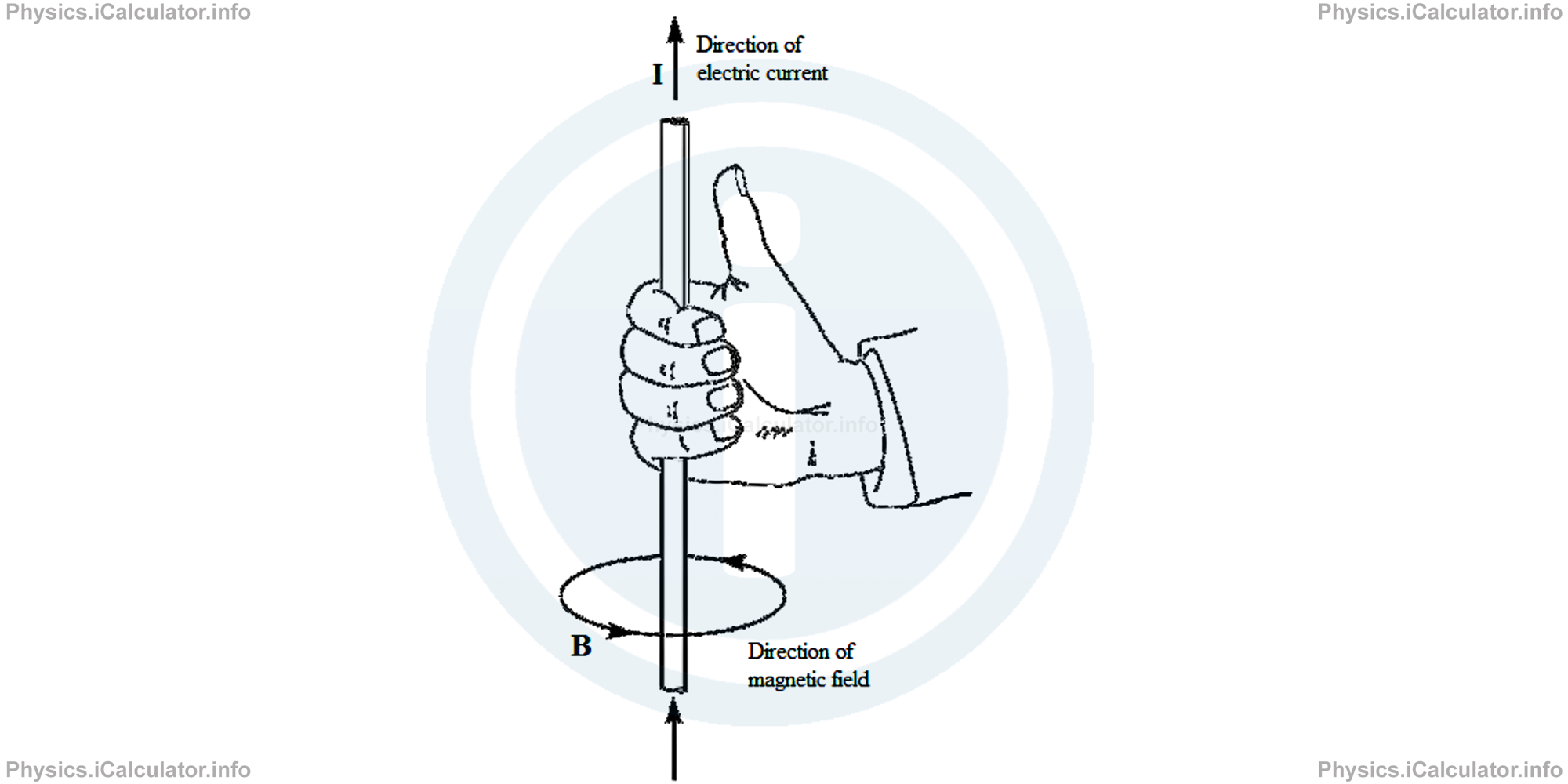
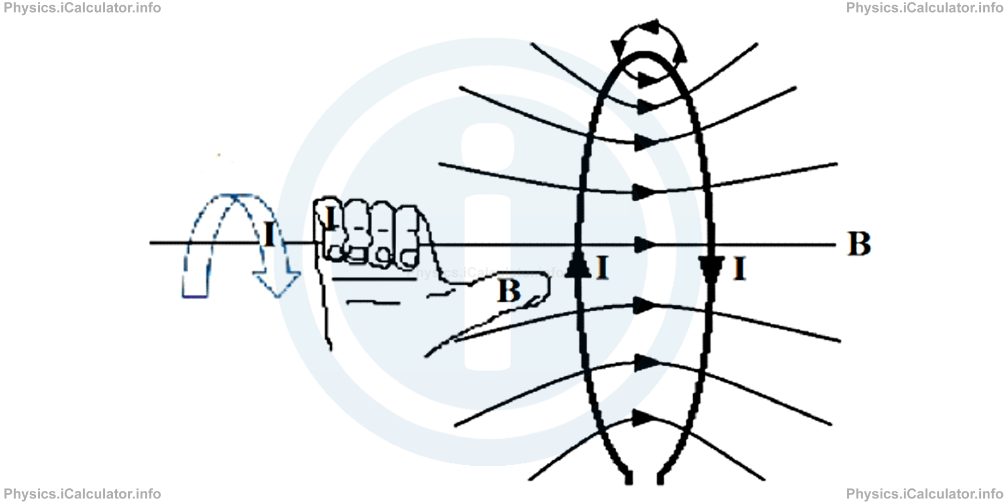
In this part of the tutorial, we will discuss about the magnetic field produced through a number of methods. They vary from each other in formulae but have one thing in common: the direction of magnetic field is found using the so-called "right-hand rule." It consists on grasping the wire by the right hand where the thumb lies in the direction of current flow. The other four fingers show the direction of magnetic field as shown in the figure.
a. Magnetic Field Produced by a Long Straight Wire
When introducing the Oersted experiment, we pointed out the fact that the needle of compass deflects from its normal direction when placed near a current carrying wire. The direction of magnetic field produced by a long current wire is found using the right-hand rule discussed in the previous paragraph.
In addition, when introducing the concept of magnetic induction (which is a quantity related to the magnetic field strength), we explained that magnetic field is inversely proportional to the distance r from the current carrying wire and directly proportional to the magnitude of current I. This joint proportionality is written as
A proportion becomes equality when multiplying the expression by a constant. Since the magnetic field around a long current carrying wire is circular, we obtain equal values for magnetic induction is constant in the entire circumference of the circle of radius r around the wire.
In addition, during the calculations we must consider a quantity similar to the vacuum permittivity ϵ0 which is used in formulae when dealing with electric field. This quantity is a constant known as the magnetic permeability of free space (vacuum), μ0. It has a value of
Thus, when considering all the above factors, the formula of magnetic induction (in scalar form) produced by a long current carrying wire is
Example 2
- What is the magnetic induction at a distance of 40 cm from a long conducting wire carrying a 0.3 A current?
- What is the direction of magnetic field if the current Is flowing vertically down?
Solution 2
Clues:
r = 40 cm = 0.40 m
I = 0.3 A
μ0 = 4π × 10-7 N/A2
a) B = ?
b) Direction of B = ?
- From the equation of magnetic induction in a long current carrying conducting wire, we have: B = μ0 ∙ I/2π ∙ r
= 4π × 10-7 N/A2 ∙ 0.3 A/2π ∙ 0.40 m
= 0.75 × 10⁻⁷ N/A ∙ m
= 7.5 × 10⁻⁸ T - When applying the right hand rule as shown in the figure below,
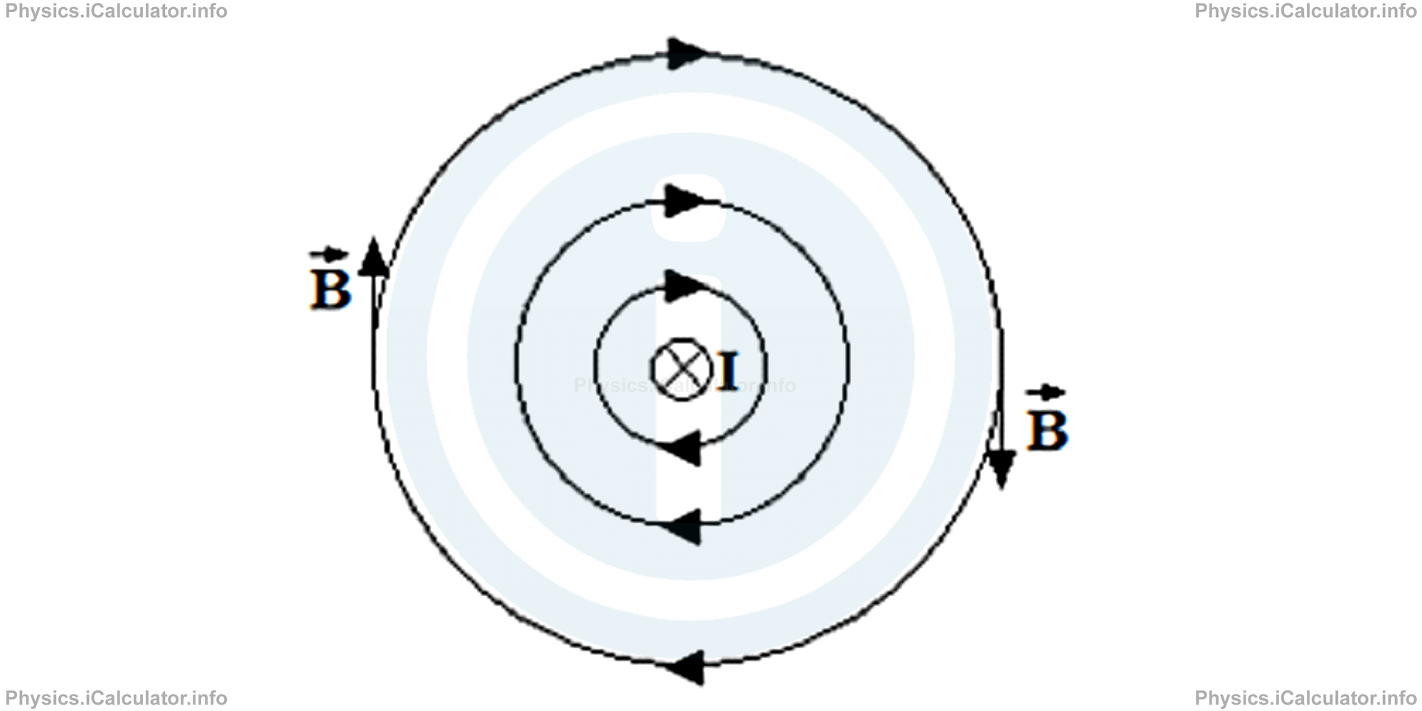
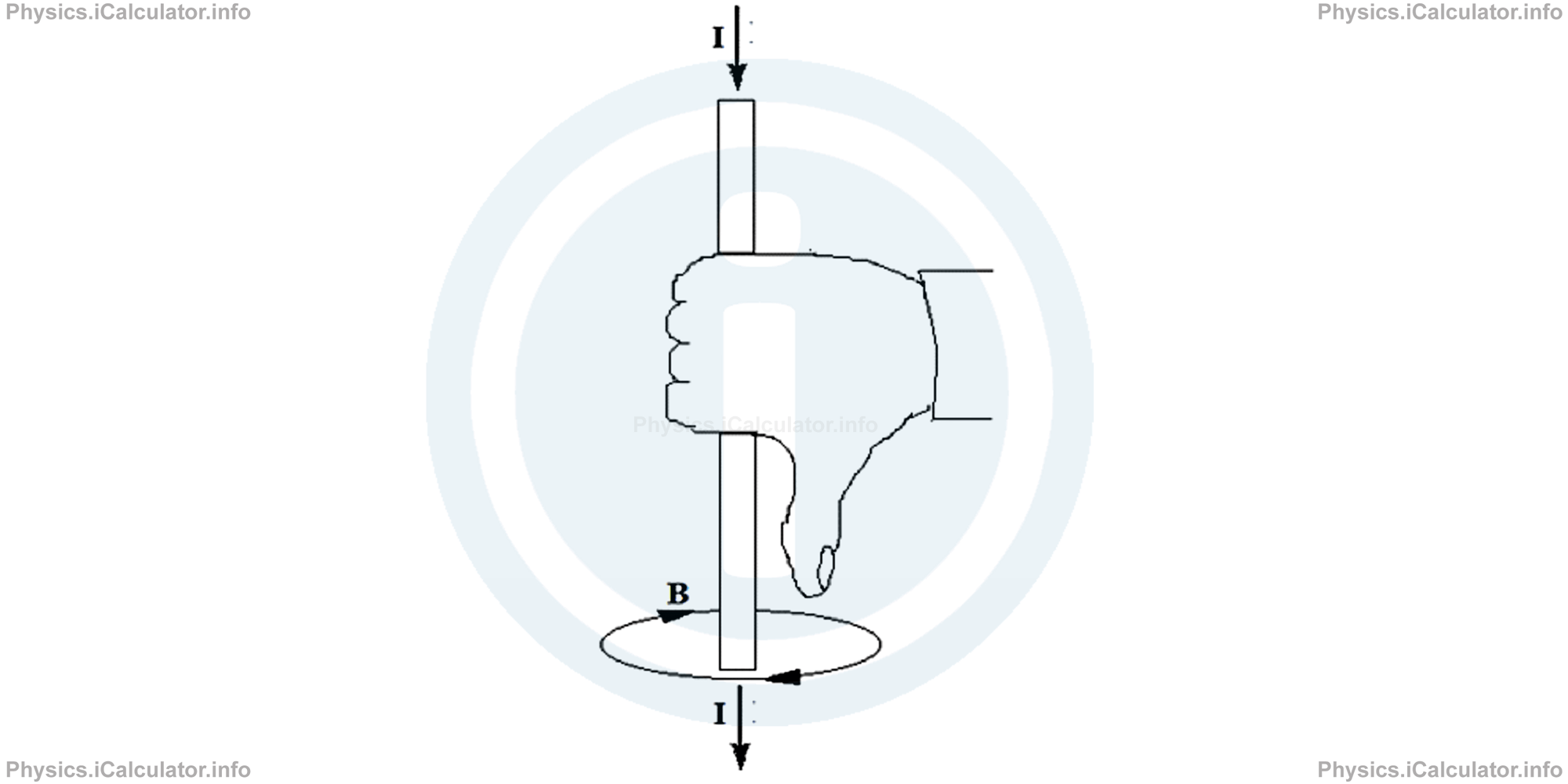 we find the direction of magnetic induction shown by the four fingers as shown in the figure. We say the direction of magnetic induction is clockwise when looked from up. Since it is impossible to plot a 3-D figure every time we have to solve such exercises, we use a simpler notation to represent the direction of current when the situation is viewed from up. Thus, when the current enters the paper we use a x-symbol inside a circle while when the current Is flowing out of paper, we use a dot inside a circle to represent the direction of current. The magnetic field is easier when using such notation, as we have only to write concentric circles to represent it. Look at the figure:
 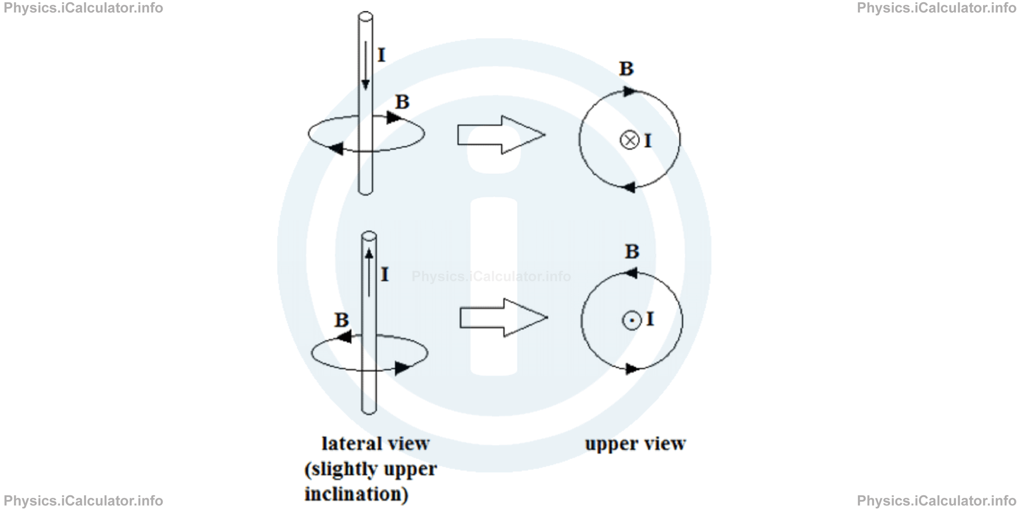 The above symbols are also used to represent the direction of magnetic field (induction) direction when a 3-D figure must be expressed in two dimensions only. Look at the figure.
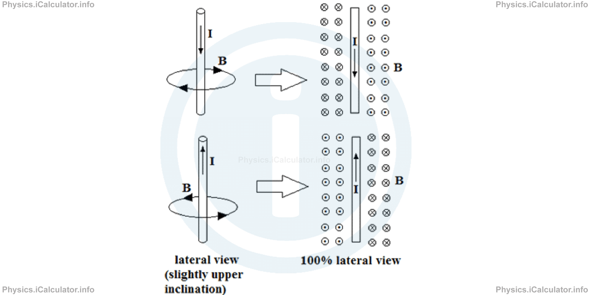
Example 3
Two long parallel wires carrying currents of I and 3I respectively, have a distance d from each other. Calculate the resultant magnetic field at any midpoint position if:
- The currents have the same direction
- The currents have opposite direction
Solution 3
- When two parallel wires have currents flowing in the same direction, they will produce magnetic fields in opposite direction at any midpoint d/2 between them. Look at the figure below:
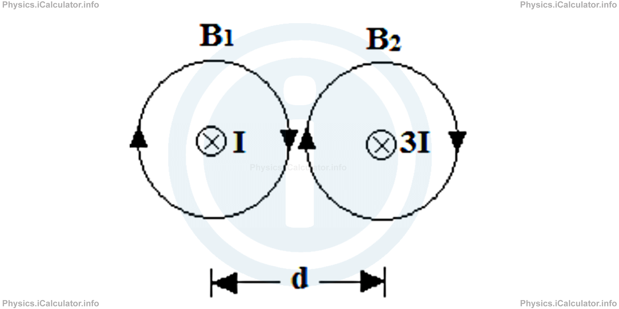 The magnetic induction B1 at the distance d/2 from the wire I is B1 = μ0 ∙ I/2π ∙ d/2The magnetic induction B2 at the distance - d/2 from the wire 3I is
= μ0 ∙ I/π ∙ dB2 = μ0 ∙ 3I/2π ∙ (- d/2)(The negative sign is because the second wire is on the other side of midpoint to the first wire.)
= -3μ0 ∙ I/π ∙ d
= -3B1
Therefore, the net magnetic induction at the midpoint of the two wires isB = B1 + B2(Or we can say "the net magnetic induction is 2B1 in the direction of the second field.")
= B1 - 3B1
= -2B1 - When the currents flowing in the parallel wires are in opposite directions, we obtain two magnetic fields in the same direction at any midpoint as shown in the figure.
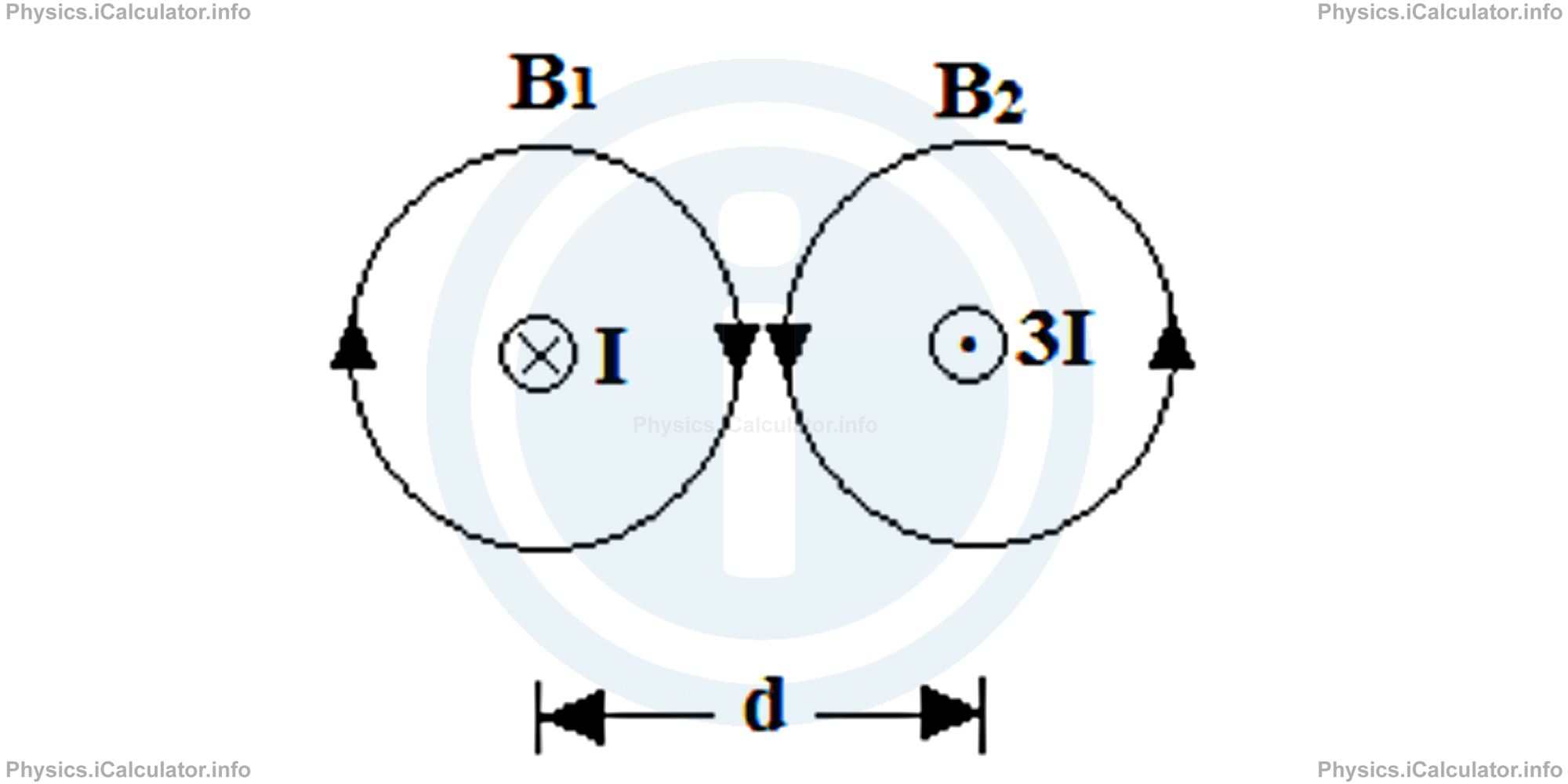 Thus, for the first magnetic induction B1 at the distance d/2 we have B1 = μ0 ∙ I/2π ∙ d/2and the second magnetic induction B2 is
= μ0 ∙ I/π ∙ dB2 = - μ0 ∙ 3I/2π ∙ d/2(Here, we have two negative signs: one for the position of the second wire in respect to the midpoint and the other for the direction of magnetic field produced by the second wire which is opposite to that of the first wire because currents are antiparallel.)
= 3μ0 ∙ I/π ∙ d
= 3B1
Therefore, the net magnetic induction at midpoint between the wires isBnet = B1 + B2
= B1 + 3B1
= 4B1
Since the intensity of magnetic field decreased with the increase in distance from the current carrying wire, we also decrease the intensity of magnetic field lines when representing it visually to give the idea of a weaker magnetic field when moving away from the wire as shown in the figure.
b. Magnetic Field of a Current-Carrying Loop
If a current flows in a circular loop as shown in the figure below, the four curled fingers are placed in the direction of electric current while the thumb shows the direction of magnetic field.
The magnetic field at the centre of a circular loop of radius r is perpendicular to the plane of the loop as shown in the figure.
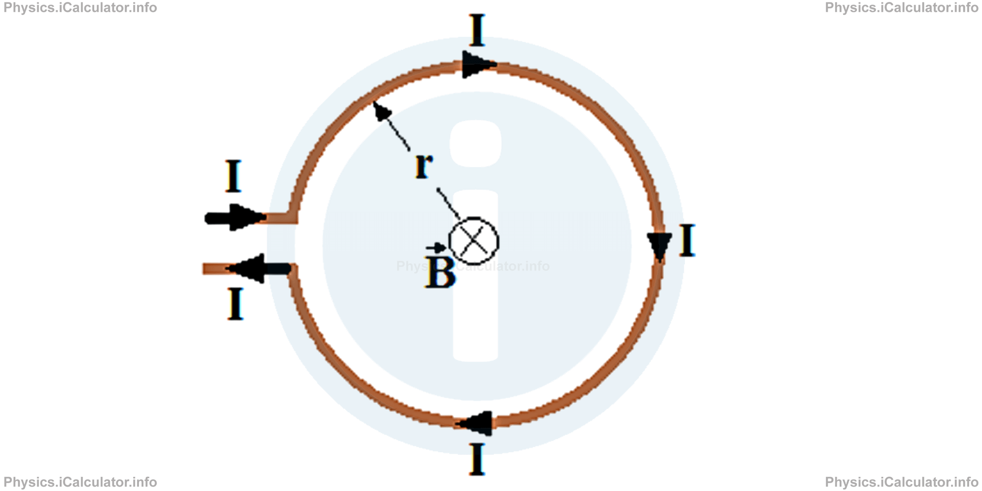
Its magnitude is given by the formula:
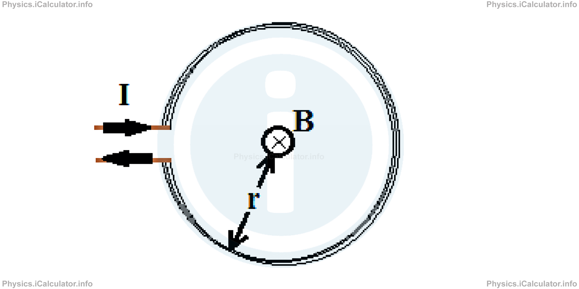
If the loop has many turns (N turns), we obtain a flat coil with a single radius. Thus, we obtain for the magnetic field at centre of coil:
Example 4
A circular loop containing 200 turns has a magnetic field of 0.2mT at its centre when a 5 A current Is flowing through it. What is the radius of loop?
Clues:
N = 200 turns = 2 × 10² turns
B = 20 mT = 2 × 10⁻² T
I = 5 A
(μ0 = 4π × 10-7 N/A2)
r = ?
Solution 4
From the formula of magnetic field at centre of a loop with N turns, we have
Rearranging for the radius r, we obtain
= (2 × 10² ) ∙ (4 ∙ 3.14 × 10⁻⁷ N/A2 ) ∙ (5A)/2 ∙ (2 × 10⁻² T)
= 3.14 × 10⁻² m
= 3.14 cm
If there are two or more current carrying wires of different shapes, the magnetic field at a given position is the net magnetic field of each individual wire at the given point. Let's clarify this point through an example.
Example 5
Two antiparallel current carrying wires having magnitudes of 4A and 5A respectively are 20 cm apart as shown in the figure. The 4A wire has a semi-circular shape of radius 40 cm around the point O. 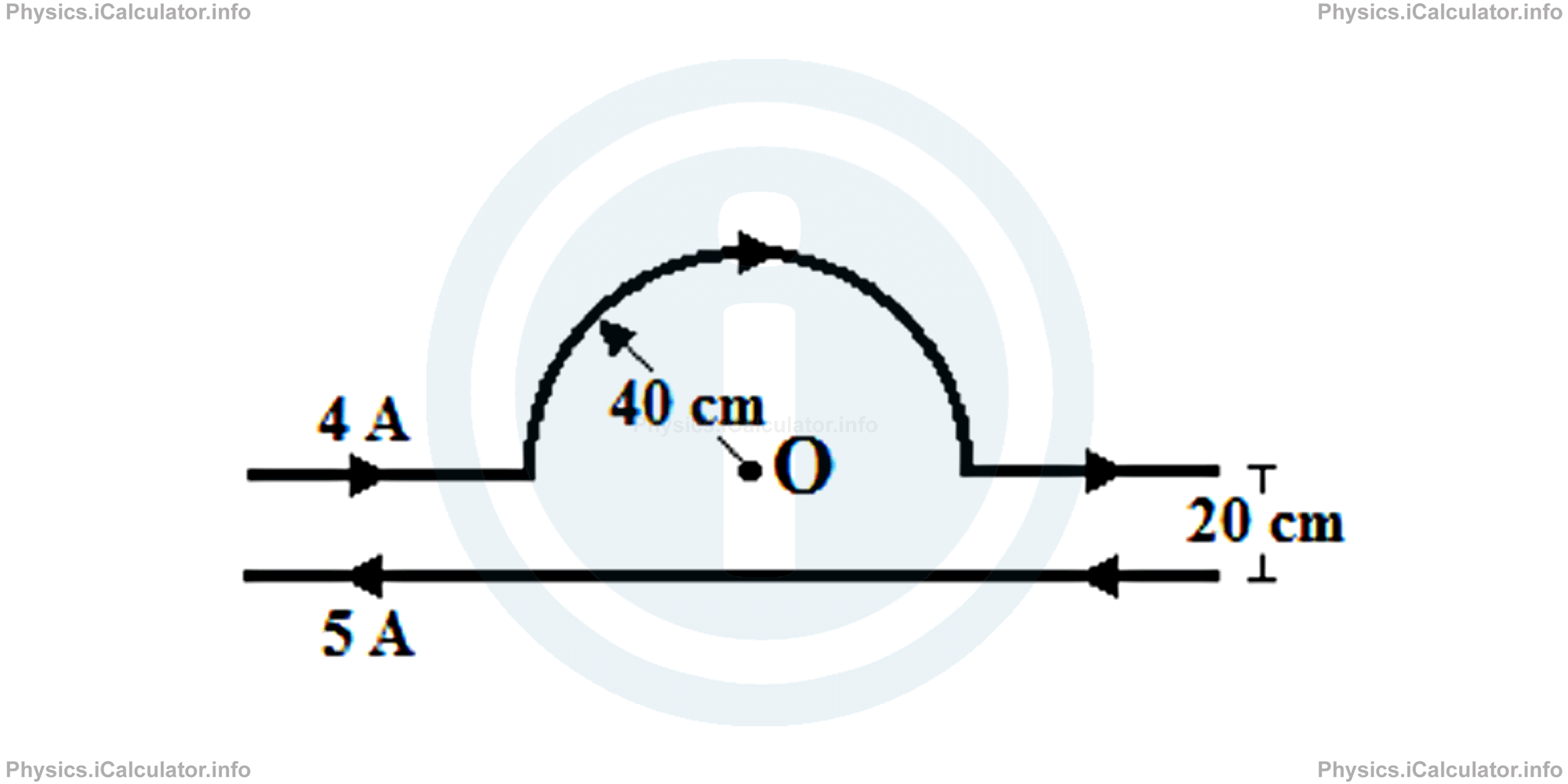
- What is the direction of magnetic field at the point O?
- What is the net magnetic induction at this point?
Solution 5
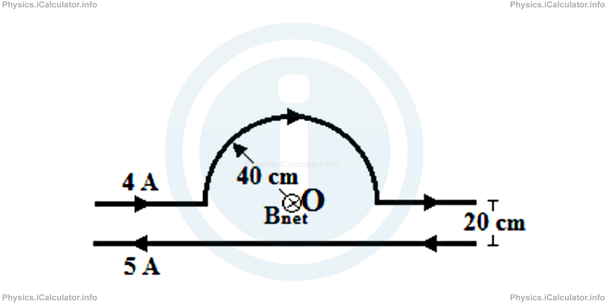
- Let's use the two right-hand rules discussed earlier to find the direction of each magnetic field. Thus, for the loop we curl the four fingers of the right hand in the direction of the 4A current and as a result, the thumb showing the direction of magnetic field will be directed inwards the page, while for the 5 A current we grasp the wire with the right hand where the thumb shows the current. Hence, the four curled fingers will show the direction of magnetic field. In this way, we find that both magnetic fields are normal to the page in the inwards direction (we must use the symbol ⊗ to show the direction for both magnetic fields).
- The magnitude of the 4A wire at centre of the loop is B1 = 1/2 ∙ μ0 ∙ I/2r(The coefficient 1/2 is because the loop's shape is semi-circular.)
Hence, substituting the values, we obtain for the first magnetic induction (giving that r = 40 cm = 0.4 m):B1 = (4 ∙ 3.14 × 10⁻⁷ N/A2 ) ∙ (4A)/4 ∙ (0.4 m)As for the magnetic field produced by the 5A (straight) wire, we obtain
= 3.14 × 10-6 TB2 = μ0 ∙ I/2π ∙ rTherefore, the net magnetic field at the point O is
= (4 ∙ 3.14 × 10⁻⁷ N/A2 ) ∙ (5A)/2 ∙ 3.14 ∙ (0.4 m)
= 2.5 × 10⁻⁶ TBnet = B1 + B2
= 3.14 × 10⁻⁶ T + 2.5 × 10⁻⁶ T
= 5.64 × 10⁻⁶ T
= 5.64 μT
c. Magnetic Field Produced by a Solenoid
As explained earlier, a solenoid is a spring-like conducting wire in which a current I flows. The wire is very long because the magnitude of magnetic field depends on the number of turns, as discussed in the previous paragraph.
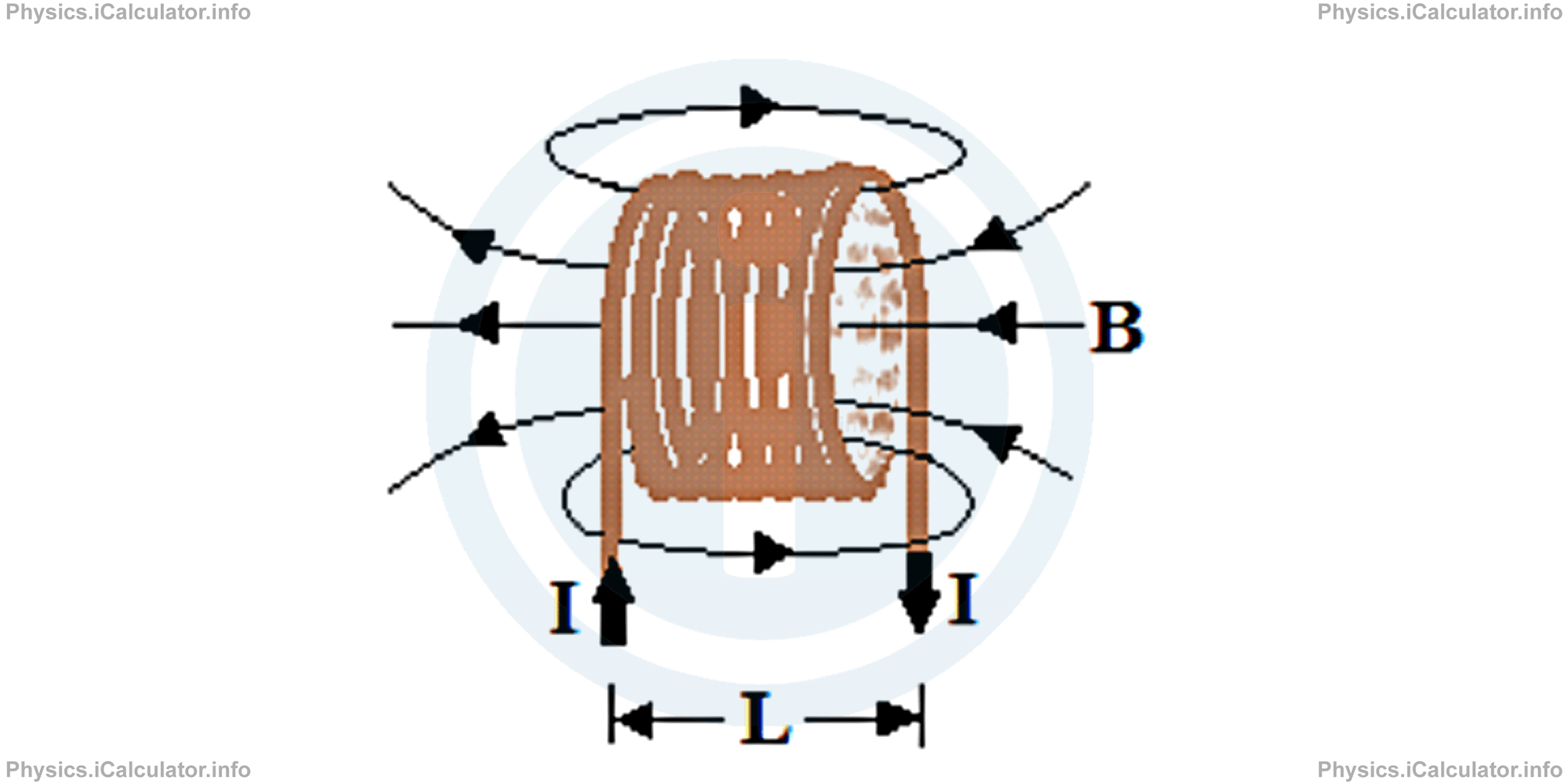
The solenoid turns are assumed as closely packed to each other so that there are no spaces between any two adjacent turns, where each turn represents an individual coil.
The magnetic field outside the solenoid is weak and non-uniform, so we can focus mainly on the magnetic field inside the solenoid. If the solenoid's length L is much longer that the diameter of turns, the magnetic field lines are linear and parallel to each other, similar to the magnetic field inside a bar magnet (the external magnetic field is similar to that of a bar magnet as well). The direction of this magnetic field is found by applying the right hand rule. Thus, for the direction of current shown in the figure above, we determine the direction of the corresponding magnetic field.
In this way, one end of the solenoid acts like a north magnetic pole while the other end as a south magnetic pole, as shown in the figure.
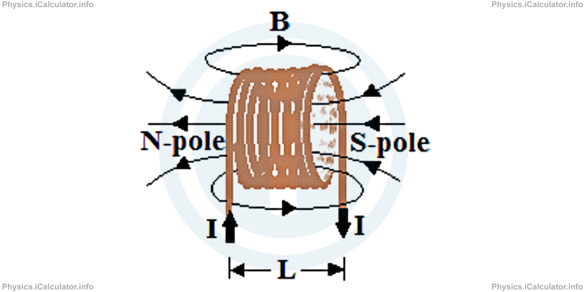
The magnitude of magnetic induction (field) inside a solenoid of length L containing N turns when a current I flows through it, is
If we write n instead of N/L, where n represents the number of turns per unit length, the above equation becomes
From the above equation we conclude that magnetic field inside a solenoid is directly proportional to the number of turns per unit length and the amount of current flowing through the solenoid.
Example 6
A 5A current flows through a 30-cm long solenoid containing 500 turns. Calculate the magnetic induction inside the solenoid. Take the figure in the theory as a reference.
Solution 6
In this problem, we have the following clues:
I = 5 A
L = 30 cm = 0.30 m
N = 500 = 5 × 10²
(μ0 = 4π × 10-7 N/A2)
B = ?
Using the equation of magnetic induction inside a solenoid,
we obtain after substitutions:
= 1.047 × 10⁻² T
As you see, this value of magnetic field is considerably higher than the magnetic fields produced by individual straight wires discussed in the previous examples. Therefore, solenoid is a great tool used to obtain a strong magnetic field in a narrow space. You can find many examples of solenoids in electric appliances such as in inductors, electromagnets, antennas, valves and many more devices in which a strong magnetic field is required.
You have reached the end of Physics lesson 16.2.3 Magnetic Field Produced by Electric Currents. Right Hand Rule. There are 4 lessons in this physics tutorial covering Magnetic Field Produced by Electric Currents, you can access all the lessons from this tutorial below.
More Magnetic Field Produced by Electric Currents Lessons and Learning Resources
Whats next?
Enjoy the "Magnetic Field Produced by Electric Currents. Right Hand Rule" physics lesson? People who liked the "Magnetic Field Produced by Electric Currents lesson found the following resources useful:
- Right Hand Rule Feedback. Helps other - Leave a rating for this right hand rule (see below)
- Magnetism Physics tutorial: Magnetic Field Produced by Electric Currents. Read the Magnetic Field Produced by Electric Currents physics tutorial and build your physics knowledge of Magnetism
- Magnetism Revision Notes: Magnetic Field Produced by Electric Currents. Print the notes so you can revise the key points covered in the physics tutorial for Magnetic Field Produced by Electric Currents
- Magnetism Practice Questions: Magnetic Field Produced by Electric Currents. Test and improve your knowledge of Magnetic Field Produced by Electric Currents with example questins and answers
- Check your calculations for Magnetism questions with our excellent Magnetism calculators which contain full equations and calculations clearly displayed line by line. See the Magnetism Calculators by iCalculator™ below.
- Continuing learning magnetism - read our next physics tutorial: Magnetic Force on a Current Carrying Wire. Ampere's Force
Help others Learning Physics just like you
Please provide a rating, it takes seconds and helps us to keep this resource free for all to use
We hope you found this Physics lesson "Magnetic Field Produced by Electric Currents" useful. If you did it would be great if you could spare the time to rate this physics lesson (simply click on the number of stars that match your assessment of this physics learning aide) and/or share on social media, this helps us identify popular tutorials and calculators and expand our free learning resources to support our users around the world have free access to expand their knowledge of physics and other disciplines.
Magnetism Calculators by iCalculator™
- Angular Frequency Of Oscillations In Rlc Circuit Calculator
- Calculating Magnetic Field Using The Amperes Law
- Capacitive Reactance Calculator
- Current In A Rl Circuit Calculator
- Displacement Current Calculator
- Electric Charge Stored In The Capacitor Of A Rlc Circuit In Damped Oscillations Calculator
- Electric Power In A Ac Circuit Calculator
- Energy Decay As A Function Of Time In Damped Oscillations Calculator
- Energy Density Of Magnetic Field Calculator
- Energy In A Lc Circuit Calculator
- Faradays Law Calculator
- Frequency Of Oscillations In A Lc Circuit Calculator
- Impedance Calculator
- Induced Emf As A Motional Emf Calculator
- Inductive Reactance Calculator
- Lorentz Force Calculator
- Magnetic Dipole Moment Calculator
- Magnetic Field At Centre Of A Current Carrying Loop Calculator
- Magnetic Field In Terms Of Electric Field Change Calculator
- Magnetic Field Inside A Long Stretched Current Carrying Wire Calculator
- Magnetic Field Inside A Solenoid Calculator
- Magnetic Field Inside A Toroid Calculator
- Magnetic Field Produced Around A Long Current Carrying Wire
- Magnetic Flux Calculator
- Magnetic Force Acting On A Moving Charge Inside A Uniform Magnetic Field Calculator
- Magnetic Force Between Two Parallel Current Carrying Wires Calculator
- Magnetic Potential Energy Stored In An Inductor Calculator
- Output Current In A Transformer Calculator
- Phase Constant In A Rlc Circuit Calculator
- Power Factor In A Rlc Circuit Calculator
- Power Induced On A Metal Bar Moving Inside A Magnetic Field Due To An Applied Force Calculator
- Radius Of Trajectory And Period Of A Charge Moving Inside A Uniform Magnetic Field Calculator
- Self Induced Emf Calculator
- Self Inductance Calculator
- Torque Produced By A Rectangular Coil Inside A Uniform Magnetic Field Calculator
- Work Done On A Magnetic Dipole Calculator