Menu
Physics Lesson 16.15.2 - Equation of the Damped Oscillations in a RLC Circuit
Please provide a rating, it takes seconds and helps us to keep this resource free for all to use
Welcome to our Physics lesson on Equation of the Damped Oscillations in a RLC Circuit, this is the second lesson of our suite of physics lessons covering the topic of Introduction to RLC Circuits, you can find links to the other lessons within this tutorial and access additional physics learning resources below this lesson.
Equation of the Damped Oscillations in a RLC Circuit
In the previous tutorial, we have explained that the total electromagnetic energy in a LC circuit is
When a resistor is added in this circuit, the total electromagnetic energy will decrease at a rate of
because some of the energy in the system turns into thermal energy of resistor and is dissipated in the environment in the form of heat energy. The negative sign in the equation means that the total energy of the system decreases.
Differentiating the above equation with time, we obtain
Since i = dQ/dt, and di/dt = d2 Q/dt2 we obtain
L ∙ dQ/dt ∙ d2 Q/dt2 + R ∙ (dQ/dt)2 + Q/C ∙ dQ/dt = 0
Simplifying both sides of the last equation by dQ/dt, we obtain
This is the differential equation for the damped oscillations in a RLC circuit.
The charge decay in such a circuit is calculated through an expression, which is a combination of exponential and sinusoidal equation, as occurs in all types of damped oscillations. Thus, the charge left in a RLC circuit after a given time t of operation is found by:
where
is the angular frequency of damped oscillations and
is the angular frequency of undamped oscillations.
In addition, you can see that the amplitude also contains an exponential decaying term e-R ∙ t/2L. This means the amplitude of every successive oscillation is smaller than the previous one as the power of Euler's Number e here is negative.
Example 1
The potential difference between the plates of a 5μF capacitor connected in an alternating 50Hz RLC circuit shown in the figure is 20V and the resistance of resistor in the circuit has a value of 0.25Ω.
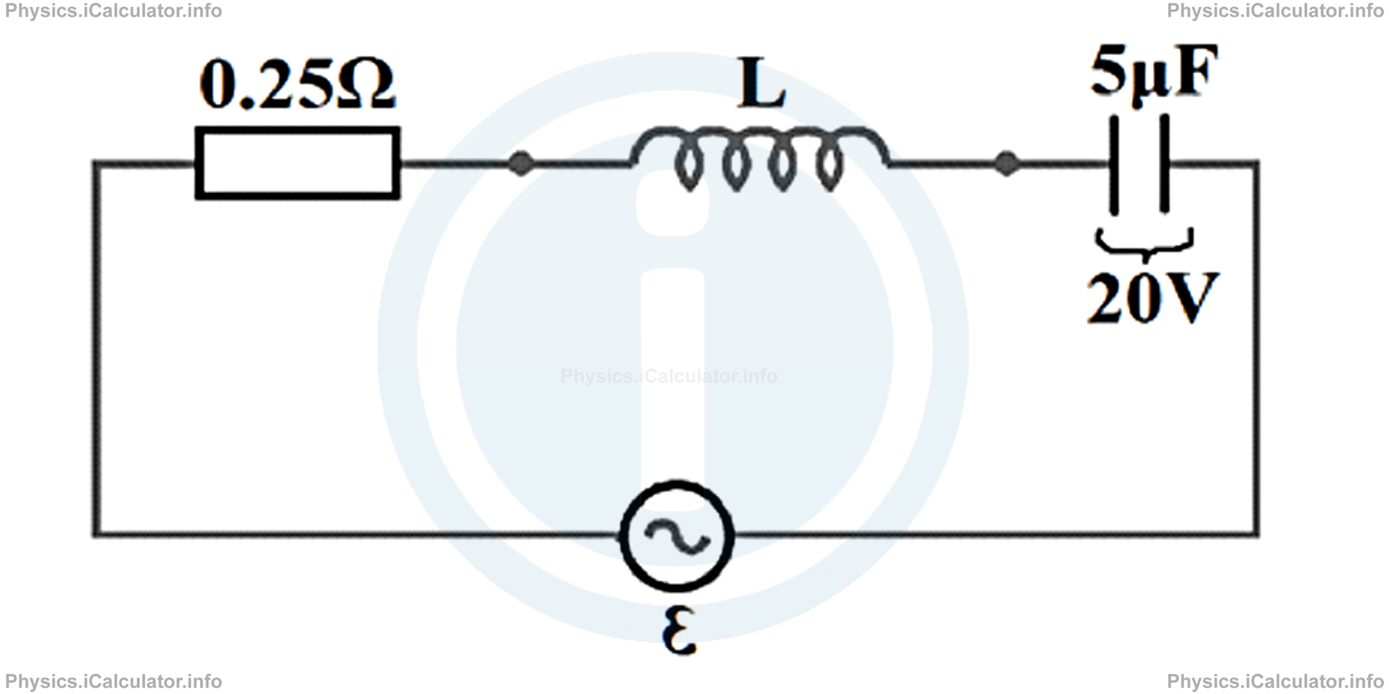
Calculate:
- The initial charge stored in the capacitor
- The charge stored in the circuit 0.4 s after the switch turns on
Take the initial phase as zero.
Solution 1
- The initial charge stored in the capacitor is Q0 = C ∙ ∆V
= (5 × 10⁻⁶ F) ∙ (20V)
= 10-4 C - First we must find the inductance and then calculate the charge stored in the circuit at the given time. Thus, since the circuit has a frequency of 50Hz, we have ω = 2π ∙ fHence, giving that
= 2π ∙ 50Hz
= 100π rad/sω = 1/√L ∙ Corω2 = 1/LCwe obtain for the inductance L of the inductor:L = 1/ω2 ∙ CThe charge stored in the capacitor after 20s therefore is
= 1/(100π)2 ∙ (10-4 )
= 1/104 ∙ π2 ∙ 10-4
= 1/π2
= 1/(3.14)2
= 0.1 HQ(t) = Q0 ∙ e-R ∙ t/2L ∙ cos(ω' ∙ t + φ)
Q(t) = Q0 ∙ e-R ∙ t/2L ∙ cos√ω2 - (R/2L)2 ∙ t
Q(20) = (10-4 ) ∙ e-0.25 ∙ 0.4/2 ∙ 0.1 ∙ cos√(100π)2 - (0.25/2 ∙ 0.1)2 ∙ 0.4
Q(20) = (10-4 ) ∙ e-5 ∙ cos(√(100π)2-(1.2)2 ∙ 0.4)
= (10-4 ) ∙ e-5 ∙ cos(100π ∙ 0.4)
= (10-4 ) ∙ e-5 ∙ cos(40π)
= (10-4 ) ∙ e-5 ∙ 1
= 10-4 ∙ 6.7 × 10-2 = 6.7 × 10⁻⁶ C
From the above results, we draw the following conclusions:
For small values of resistance, ω' ≈ ω, so we can neglect the (R/2L)2 factor and focus only on the value of ω.
We can use a similar approach when calculating the energy decay in a RLC circuit operating without an external energy supply. For this, we observe what happens to the electric energy in the capacitor. Since
we can write this expression as a function of time, i.e.
= [Q0 ∙ e-R ∙ t/2L ∙ cos(ω' ∙ t + φ) ]2/2C
= Q20/2C ∙ e - R ∙ t/L ∙ cos2(ω' ∙ t + φ)
This means the energy of the electric field in a RLC circuit oscillates in a cos2 fashion while the amplitude decreases exponentially with time.
Example 2
A 50Hz RLC circuit contains a 10Ω resistor, a 0.4H inductor and a 2nF capacitor connected in series. The capacitor initially stores a charge of 5μC. Calculate:
- The initial electric energy stored in the capacitor plates
- The energy left in the capacitor plates 2 s after the switch turns OFF.
Take the initial phase equal to zero.
Solution 2
Clues:
R = 10 Ω
L = 0.4 H
C = 2nF = 2 × 10⁻⁹ F
Q0 = 5μC = 5 × 10⁻⁶ C
f = 50 Hz
a) We initial = ?
b) W(2) = ?
- The initial electric energy stored in the capacitor plates is We initial = Q20/2C
= (5 × 10⁻⁶ C)2/2 ∙ (2 × 10⁻⁹ F)
= 6.25 × 10⁻³ J - The energy left in the capacitor plates after 2 s of supply interruption is We (t) = Q20/2C ∙ e - R ∙ t/L ∙ cos2(ω' ∙ t + φ)This value is very small, close to zero. Hence, we say the flow of energy through a RLC circuit, practically stops immediately after the switch turns off. Again, here you can see how necessary a sustainable external source such as a battery or an AC power supply is, in order to maintain constant the electricity flow through a RLC circuit.
We (t) = Q20/2C ∙ e - R ∙ t/L ∙ cos2(√ω2-(R/2L)2 ∙ t)
We (2) = (6.25 × 10⁻³ J) ∙ e-10 ∙ 2/0.4 ∙ cos2√(2 ∙ π ∙ 50)2-(10/2 ∙ 0.4)2 ∙ 2
= (6.25 × 10⁻³ J) ∙ e-50 ∙ cos2(√98596 - 156.25 ∙ 2)
= (6.25 × 10⁻³ J) ∙ e-50 ∙ cos2(√98439.75 ∙ 2)
= (6.25 × 10⁻³ J) ∙ e-50 ∙ cos2(627.5 rad)
= (6.25 × 10⁻³ J) ∙ (1.93 × 10⁻²² ) ∙ (0.6833)2
= 5.63 × 10⁻²⁵ J
You have reached the end of Physics lesson 16.15.2 Equation of the Damped Oscillations in a RLC Circuit. There are 4 lessons in this physics tutorial covering Introduction to RLC Circuits, you can access all the lessons from this tutorial below.
More Introduction to RLC Circuits Lessons and Learning Resources
Whats next?
Enjoy the "Equation of the Damped Oscillations in a RLC Circuit" physics lesson? People who liked the "Introduction to RLC Circuits lesson found the following resources useful:
- Equation Feedback. Helps other - Leave a rating for this equation (see below)
- Magnetism Physics tutorial: Introduction to RLC Circuits. Read the Introduction to RLC Circuits physics tutorial and build your physics knowledge of Magnetism
- Magnetism Revision Notes: Introduction to RLC Circuits. Print the notes so you can revise the key points covered in the physics tutorial for Introduction to RLC Circuits
- Magnetism Practice Questions: Introduction to RLC Circuits. Test and improve your knowledge of Introduction to RLC Circuits with example questins and answers
- Check your calculations for Magnetism questions with our excellent Magnetism calculators which contain full equations and calculations clearly displayed line by line. See the Magnetism Calculators by iCalculator™ below.
- Continuing learning magnetism - read our next physics tutorial: The Series RLC Circuit
Help others Learning Physics just like you
Please provide a rating, it takes seconds and helps us to keep this resource free for all to use
We hope you found this Physics lesson "Introduction to RLC Circuits" useful. If you did it would be great if you could spare the time to rate this physics lesson (simply click on the number of stars that match your assessment of this physics learning aide) and/or share on social media, this helps us identify popular tutorials and calculators and expand our free learning resources to support our users around the world have free access to expand their knowledge of physics and other disciplines.
Magnetism Calculators by iCalculator™
- Angular Frequency Of Oscillations In Rlc Circuit Calculator
- Calculating Magnetic Field Using The Amperes Law
- Capacitive Reactance Calculator
- Current In A Rl Circuit Calculator
- Displacement Current Calculator
- Electric Charge Stored In The Capacitor Of A Rlc Circuit In Damped Oscillations Calculator
- Electric Power In A Ac Circuit Calculator
- Energy Decay As A Function Of Time In Damped Oscillations Calculator
- Energy Density Of Magnetic Field Calculator
- Energy In A Lc Circuit Calculator
- Faradays Law Calculator
- Frequency Of Oscillations In A Lc Circuit Calculator
- Impedance Calculator
- Induced Emf As A Motional Emf Calculator
- Inductive Reactance Calculator
- Lorentz Force Calculator
- Magnetic Dipole Moment Calculator
- Magnetic Field At Centre Of A Current Carrying Loop Calculator
- Magnetic Field In Terms Of Electric Field Change Calculator
- Magnetic Field Inside A Long Stretched Current Carrying Wire Calculator
- Magnetic Field Inside A Solenoid Calculator
- Magnetic Field Inside A Toroid Calculator
- Magnetic Field Produced Around A Long Current Carrying Wire
- Magnetic Flux Calculator
- Magnetic Force Acting On A Moving Charge Inside A Uniform Magnetic Field Calculator
- Magnetic Force Between Two Parallel Current Carrying Wires Calculator
- Magnetic Potential Energy Stored In An Inductor Calculator
- Output Current In A Transformer Calculator
- Phase Constant In A Rlc Circuit Calculator
- Power Factor In A Rlc Circuit Calculator
- Power Induced On A Metal Bar Moving Inside A Magnetic Field Due To An Applied Force Calculator
- Radius Of Trajectory And Period Of A Charge Moving Inside A Uniform Magnetic Field Calculator
- Self Induced Emf Calculator
- Self Inductance Calculator
- Torque Produced By A Rectangular Coil Inside A Uniform Magnetic Field Calculator
- Work Done On A Magnetic Dipole Calculator