Menu
Physics Lesson 17.2.4 - More on Components: Diodes, Potential Dividers, Reed Switches and Transistors
Please provide a rating, it takes seconds and helps us to keep this resource free for all to use
Welcome to our Physics lesson on More on Components: Diodes, Potential Dividers, Reed Switches and Transistors, this is the fourth lesson of our suite of physics lessons covering the topic of Electronic Components and Switching, you can find links to the other lessons within this tutorial and access additional physics learning resources below this lesson.
More on Components
In the following paragraphs we will explain, in greater detail, the structure and operating principle of some electronic components.
a. Diodes
As explained earlier, diodes are circuit components that let the current flow in only one direction. Since most electronic devices operate in AC circuits, the current produced by an AC source changes direction 50 times in second (50 Hertz operating frequency) in most countries and 60 times in second (60 hertz operating frequency) in the rest of world. Therefore, a current rectifier is necessary in the circuit, which lets the current flow in one direction but prevent it from flowing in the opposite direction. This function is carried out by the diode.
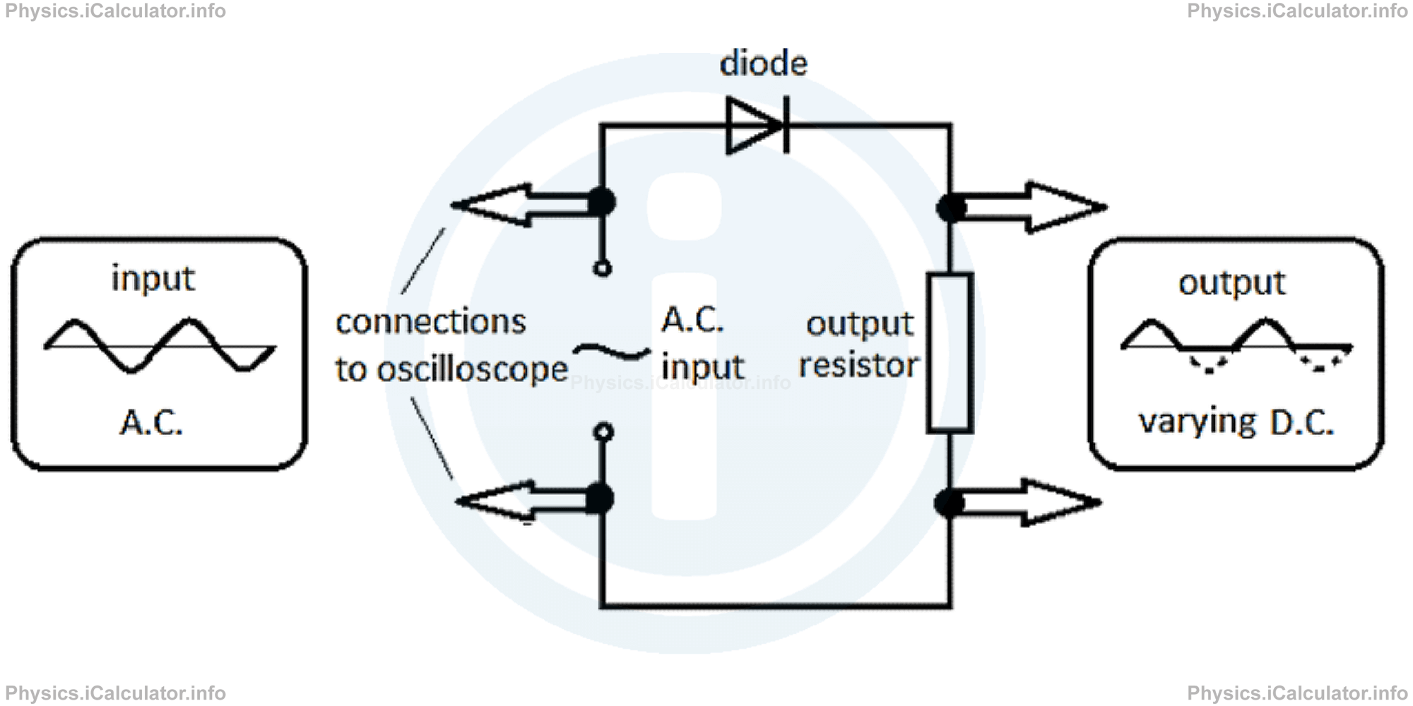
In other words, a diode is an electronic device used to change the current from AC to DC. This process is known as rectification. A diode lets the current flow in the forwards direction but blocks the backward one. The following figure shows an AC circuit containing a diode and a resistor. To make the process of current rectification visible, an oscilloscope is connected to the terminals of the input AC source so that the output waveform is shown on the screen.
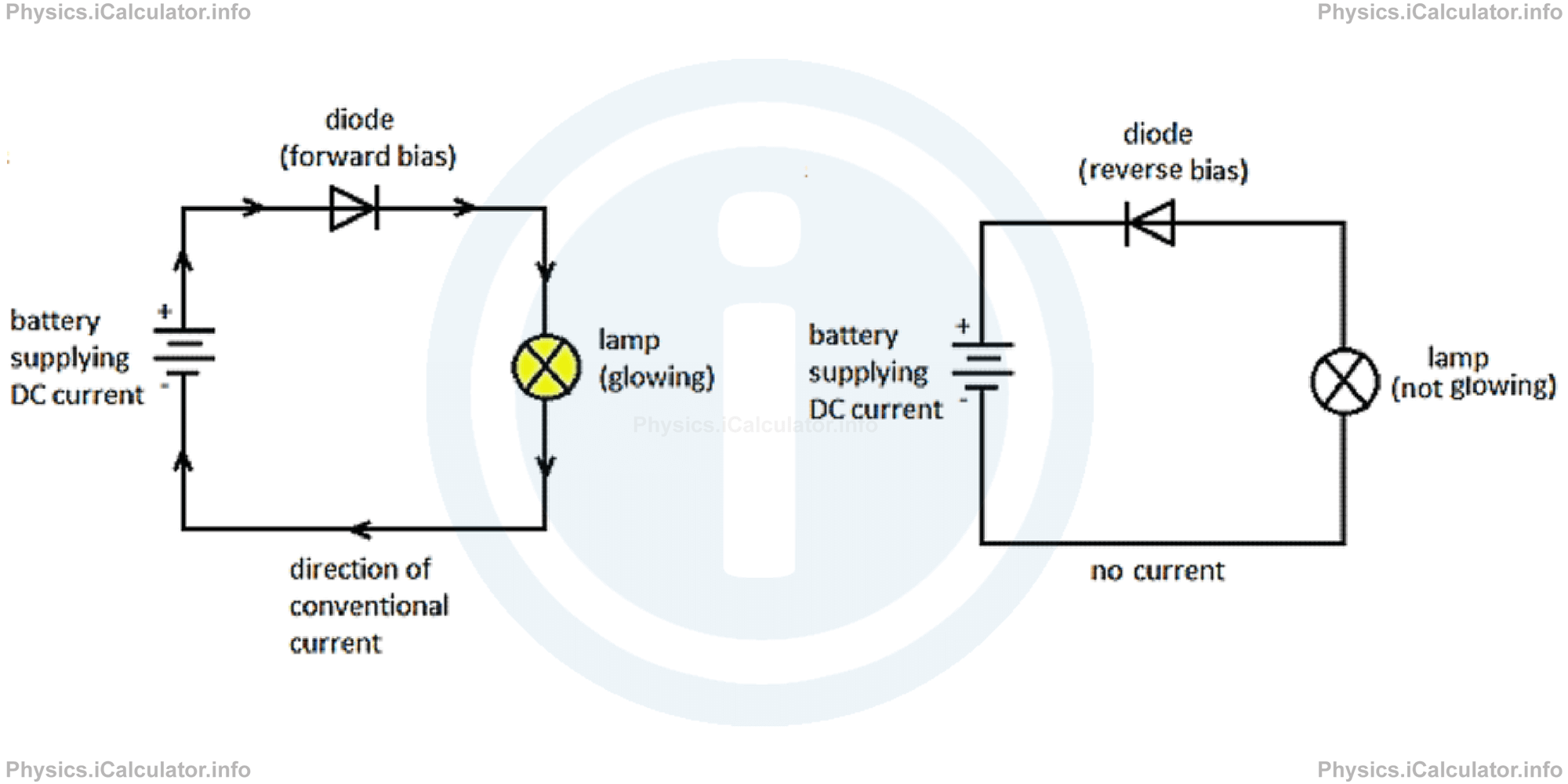
Diodes can be connected in DC circuits as well. Thus, when a diode is connected in the so-called forward-biased way, it offers a very low resistance to the current and as a result, the lamp glows bright. In this case, we can appoint a direction to the current flow, similarly to the current flow in DC circuits. On the other hand, when the same diode is connected in the reverse bias way, it offers a very high resistance to the current flow. Therefore, the lamp does not glow because the diode blocks the current. Look at the figure.
However, there is still an issue to overcome. If you look carefully the graph of output signal which represents the rectified current in the AC circuit, you can see that the current is not entirely rectified. Only in one of directions the current is rectified by the diode; in the other direction the current is still sinusoidal, as shown by the output signal. To fix this issue, we connect a capacitor across the output. The capacitor acts like a shock absorber in cars, i.e. it collects charge during the surges and releases it when the current from the rectifier falls. This makes the current flowing in the circuit be more uniform, very similar to the current produced by a DC source such as a battery. This is why diodes are so useful in electronic circuits; you can create a DC-like circuit supplied by a practically sustainable source of energy such as an AC power supply instead of using normal batteries which have a limited longevity.
b. Potential dividers
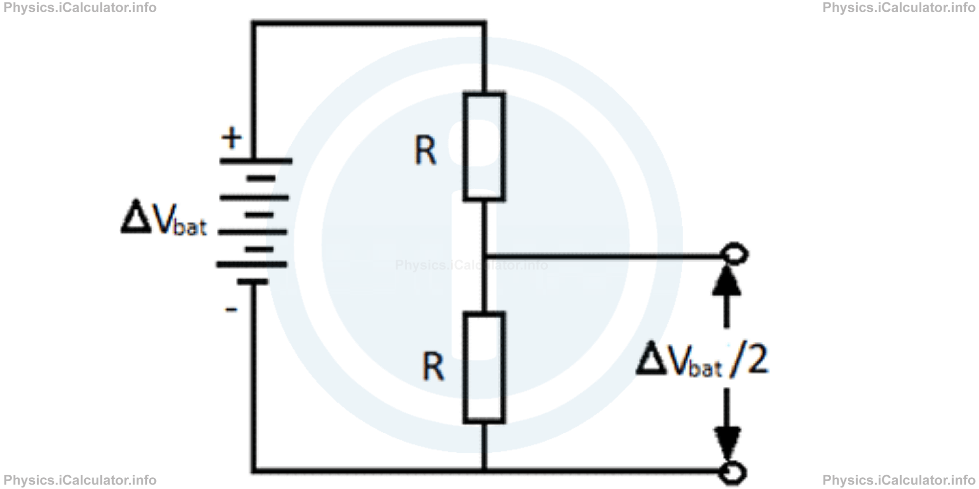
A potential divider is an arrangement used to deliver only a portion of the input potential difference produced by the source. For example, if we want to deliver only half of the input potential difference, we connect two identical resistors in series and the terminals of the potential divider are connected across one of resistors, as shown in the figure below.
We can also connect a variable resistor (rheostat) instead of the lower resistor in the figure above in order to obtain output voltages varying between 0 V and ΔVbat / 2, as shown in the figure below.
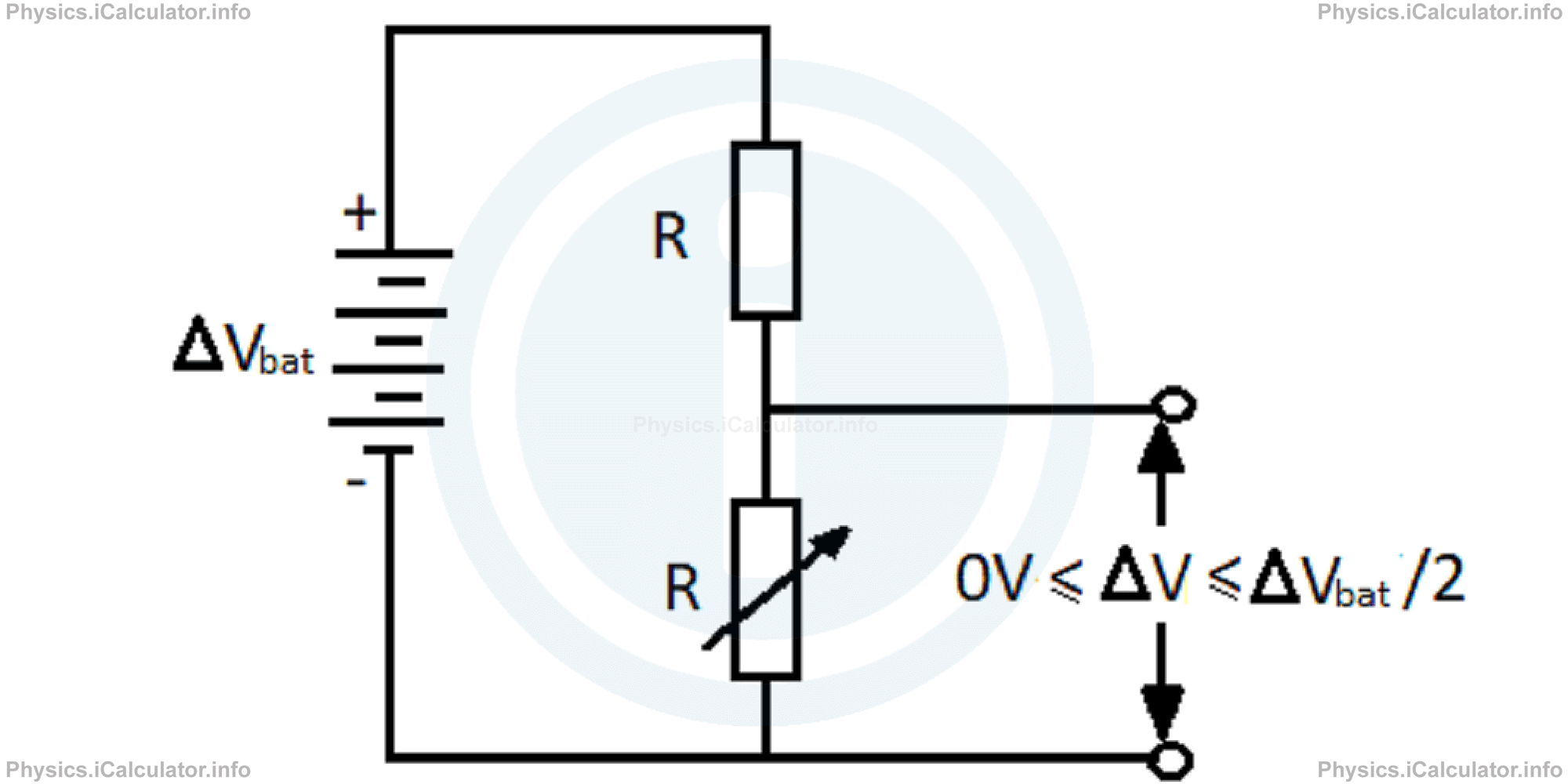
The last circuit can be used as a volume control in a radio or as light intensity controller in a dimmer switch.
Example 1
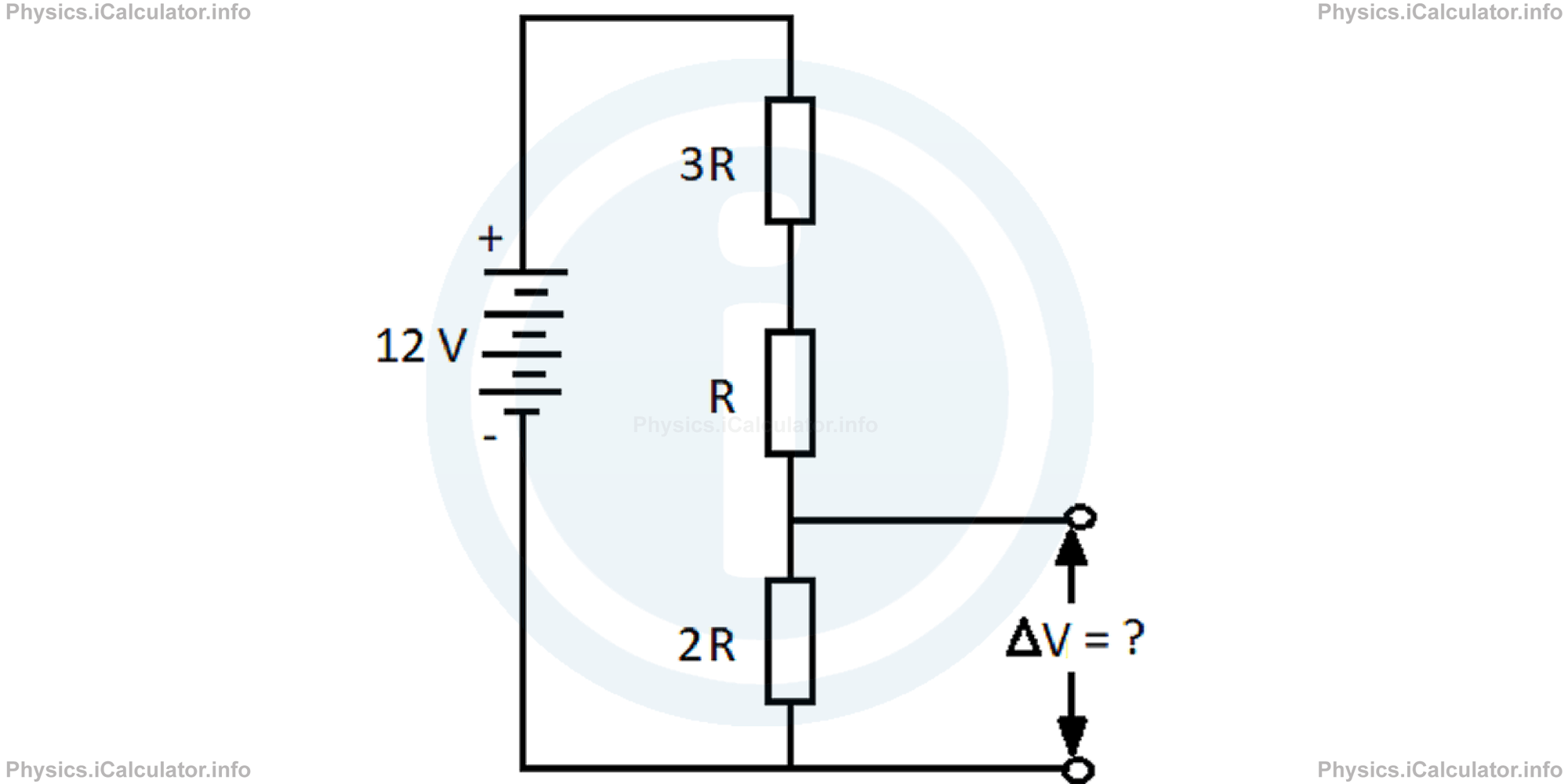
What is the output voltage across the terminals of the potential divider shown in the figure below?
Solution 1
This is a series circuit, so the current is the same everywhere. Since the total resistance of circuit is
the potential difference across the potential divider is one-third of the total potential difference produced by the battery as
Thus, after substitutions, we obtain
∆Vpot div = 12 V ∙ 2R/6R
= 4 V
c. Reed switches
A reed switch is a type of switch controlled through a magnetic field. The contact close if a magnet is brought near the switch shown in the figure below.
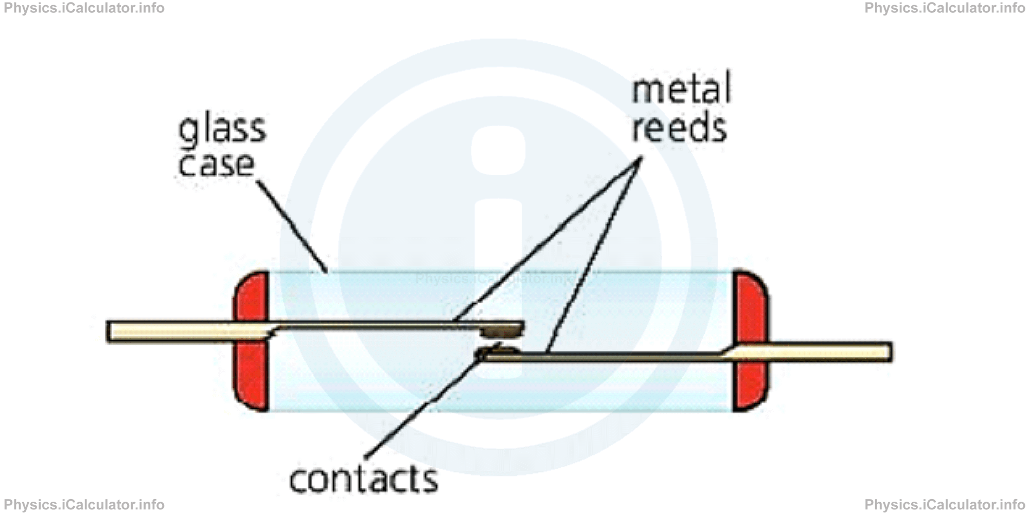
When the magnet is moved near, the reeds magnetize and as a result, they attract each other. Various alarm system contain reed switches.
A reed switch becomes a reed relay when a coil is placed round it. The current in one circuit (through the coil) switches on another circuit (through the contacts).
d. Transistors
A transistor is a semiconductor device with three connections, capable of amplification in addition to rectification. In other words, a transistor is an electronic component used in a circuit to control a large amount of current or voltage with a small amount of voltage or current. This means that it can be used to amplify or switch (rectify) electrical signals or power, allowing it to be used in a wide range of electronic devices.
The term "transistor" derives from "transfer resistor" because the current is transferred across a material that normally has high resistance such as a semiconductor. Normally, the construction of a transistor is based upon the sandwiching of one semiconductor between two other semiconductors.
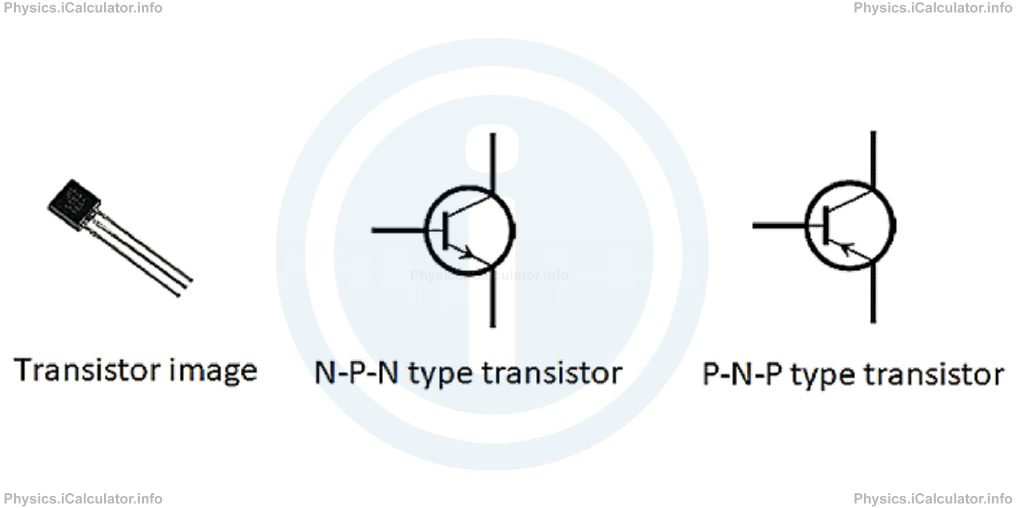
There are essentially two basic types of point-contact transistors, the N-P-N transistor and the P-N-P transistor, where the N and N stand for negative and positive, respectively, as explained earlier in this tutorial. The only difference between the two is the arrangement of bias voltages. The figure below shows the image of a transistor and the circuit symbols of the two aforementioned types of transistors.
To explain how transistors work, let's consider a N-P-N type transistor. Each end of the transistor is a N-type semiconductor material and between them is a P-type semiconductor material. If you picture such a device plugged into a battery, you'll see how the transistor works:
- the N-type region attached to the negative end of the battery helps propel electrons into the middle P-type region.
- the N-type region attached to the positive end of the battery helps slow electrons coming out of the P-type region.
- the P-type region in the center does both.
By varying the potential in each region, then, you can drastically affect the rate of electrons flow across the transistor.
The invention of transistors was a huge step in the history of electronics. The old vacuum tubes cannot be compared to transistors regarding effectiveness, applicability, adaptability, etc. A single integrated circuit used in PCs, laptops, etc., contains millions of tiny transistors, which help produce a large number of voltage variations necessary for digital computing.
At last, there is a large number of transistors depending on their application field. However, we will not deal with them here, as this goes beyond the scope of this tutorial.
You have reached the end of Physics lesson 17.2.4 More on Components: Diodes, Potential Dividers, Reed Switches and Transistors. There are 5 lessons in this physics tutorial covering Electronic Components and Switching, you can access all the lessons from this tutorial below.
More Electronic Components and Switching Lessons and Learning Resources
Whats next?
Enjoy the "More on Components: Diodes, Potential Dividers, Reed Switches and Transistors" physics lesson? People who liked the "Electronic Components and Switching lesson found the following resources useful:
- Diodes Feedback. Helps other - Leave a rating for this diodes (see below)
- Electronics Physics tutorial: Electronic Components and Switching. Read the Electronic Components and Switching physics tutorial and build your physics knowledge of Electronics
- Electronics Revision Notes: Electronic Components and Switching. Print the notes so you can revise the key points covered in the physics tutorial for Electronic Components and Switching
- Electronics Practice Questions: Electronic Components and Switching. Test and improve your knowledge of Electronic Components and Switching with example questins and answers
- Check your calculations for Electronics questions with our excellent Electronics calculators which contain full equations and calculations clearly displayed line by line. See the Electronics Calculators by iCalculator™ below.
- Continuing learning electronics - read our next physics tutorial: Electronic Essentials: Analogue and Digital Signals, Binary Operations and Logic Gates
Help others Learning Physics just like you
Please provide a rating, it takes seconds and helps us to keep this resource free for all to use
We hope you found this Physics lesson "Electronic Components and Switching" useful. If you did it would be great if you could spare the time to rate this physics lesson (simply click on the number of stars that match your assessment of this physics learning aide) and/or share on social media, this helps us identify popular tutorials and calculators and expand our free learning resources to support our users around the world have free access to expand their knowledge of physics and other disciplines.