Menu
Physics Lesson 16.12.3 - RL Circuits
Please provide a rating, it takes seconds and helps us to keep this resource free for all to use
Welcome to our Physics lesson on RL Circuits, this is the third lesson of our suite of physics lessons covering the topic of RL Circuits, you can find links to the other lessons within this tutorial and access additional physics learning resources below this lesson.
RL Circuits
The rise or fall in the number of charges in a capacitor charging through a resistor results in a rise or fall in the current in the circuit as
For very small time intervals dt, we can write
Similarly, a rise or a fall of the current occurs when a source by an electromotive force ε supplies a single loop circuit containing a resistor R and an inductor L.
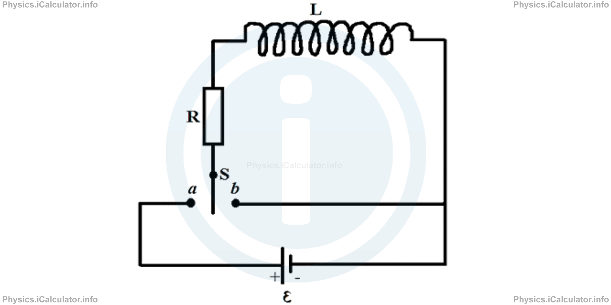
When the switch S is moved at position a, the current in the resistor starts to rise. In absence of inductor, this rise of current from zero to a steady value would be immediate and we used the Ohm's law to find this rise in current, i.e.
When an inductor is present in the circuit however, a self-induced emf εL appears in the circuit. The current generated because of this self-induced emf is in the opposite direction of the current produced by the battery. As a result, it opposes the rise in current (from the Lentz law) and this causes a delay in the rise of current in the circuit. In other words, the current in the circuit is related to the difference of the two emf's: one is the (steady) emf of battery ε and the other is the (changeable) emf self-induced εL in the inductor. This last one, has the formula
where i is the current induced in the inductor and L is its inductivity.
Over time, the rise in current due to the self-induced emf in the inductor becomes less rapid. As a result, the current in the circuit approaches the value of the steady current ε calculated through the Ohm's law. However, in presence of an inductor in the circuit, the current never reaches the ε/R value (or using the language of mathematics, we say the current reaches this limit value in an infinite time interval). Therefore, we say:
"An inductor initially opposes the rise in the current in the circuit but after a long time, it acts as a simple conducting wire."
Thus, when the switch is at position a as discussed earlier, the original circuit behaves like the simplified one shown below:
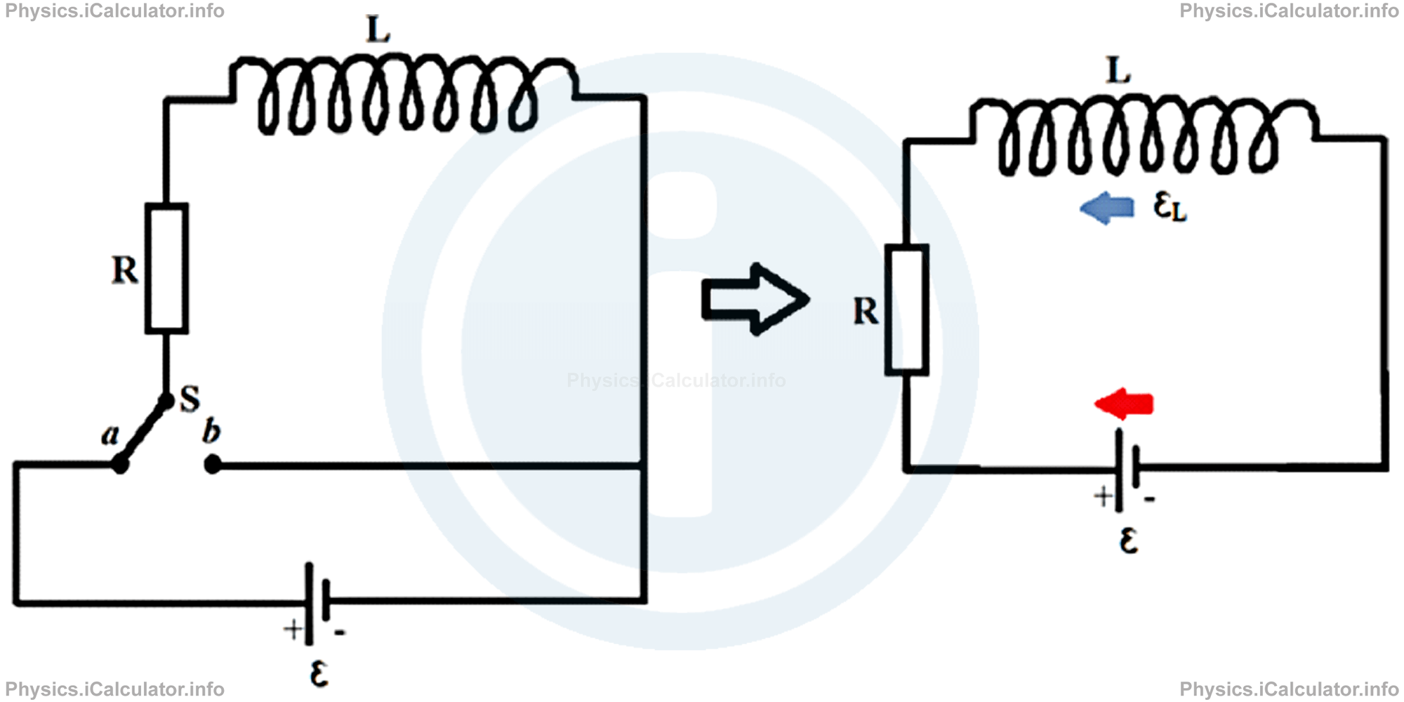
Since numerically the value of the self-induced emf in the best case can equal the value of emf produced by the battery, the current I in the circuit is in the direction of the red arrow (here clockwise). Therefore, the potential in the resistor decreases in the clockwise direction and as a result, the potential difference across the resistor R is
Likewise, since the self-induced emf in the inductor is in the opposite direction to the emf of battery, we write again
Hence, since the emf produced by the battery is clockwise, we write from the Kirchhoff's Second Law (the voltage law), which is based on the law of conservation of energy:
Or
We can rearrange the last equation to isolate ε:
The solution of this differential equation in terms of the current I, (using the differentiation techniques which you can find in the math section of this webpage), is
The form of this equation is similar to that of potential difference (and charge) in a RC circuit.
If we write the term L/R as τL (we call it "the inductive time constant), the above equation is written as
This equation is used to calculate the current at any instant when the current in the circuit is rising. When the current drops, we use the equation
to calculate the current in the circuit at any instant t.
Example 1
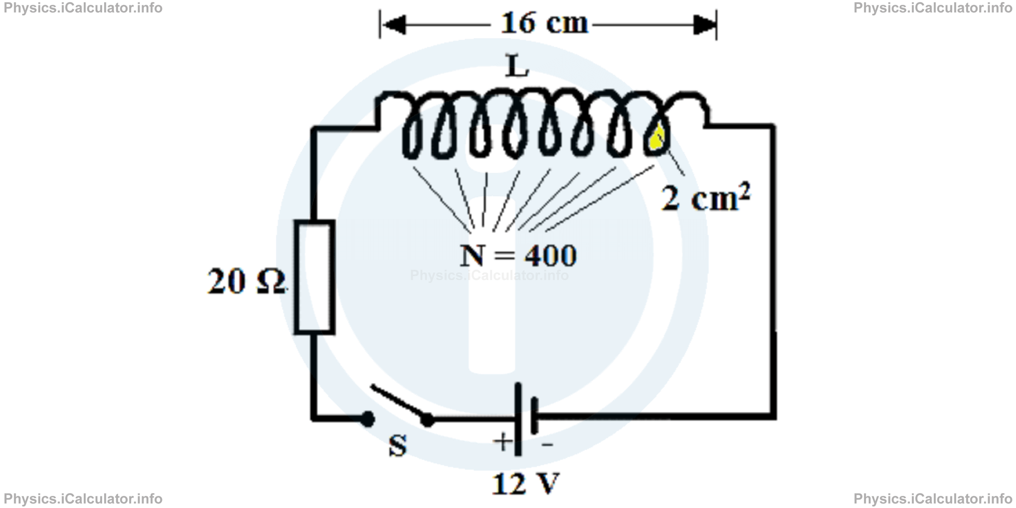
A 20 Ω resistor is connected to a 12V battery. A 16 cm long inductor having 4000 turns and the area of each loop equal to 8 cm2, is connected in series to the resistor, as shown in the figure.
Calculate:
- The current in the circuit when the switch S is in the actual position (OFF)
- The current in the circuit immediately after the switch is closed (ON)
- The current in the circuit 0.003 s after the switch is closed (ON)
- The current in the circuit 10 s after the switch is closed (ON)
- Can you find the exact time when the current becomes steady? Why?
- What is the potential difference in the resistor and inductor at t = 0.001 s?
Solution 1
- The circuit is initially open (OFF). Hence, no current is flowing through the circuit when the switch is in this position.
- We have t = 0 immediately after the switch turns ON. In this case, we use the equationi(t) = ε/R ∙ (1 - e- R ∙ t/L)to find the current in the circuit at this instant. Thus, we obtaini(t) = ε/R ∙ (1 - e- R ∙ t/L )Therefore, the current is still zero immediately after the switch turns ON, as the self-induced emf in the coil prevents the current from flowing in the circuit.
= 12/20 ∙ (1- e - 20 ∙ 0/L )
= 12/20 ∙ (1 - e0 )
= 12/20 ∙ (1 - 1)
= 12/20 ∙ 0
= 0 - Before calculating the current in other instants, we must find the self-inductance L in the inductor using the equation L = μ0 ∙ N2 ∙ A/Iwhere
N = 4000 = 4 × 10³ turns
Thus, we obtain for the self-inductance L of the inductor:
A = 8 cm2 = 8 × 10⁻⁴ m2
l = 16 cm = 0.16 m
(μ0 = 4π × 10-7 N/A2)L = (4 ∙ 3.14 ∙ 10-7 N/A2 ) ∙ (4 × 10³ )2 ∙ (8 × 10⁻⁴ m2 )/(0.16 m)The current flowing in the circuit at t = 0.003 s is:
= 10048 × 10-5 H
= 0.1 Hi(t) = ε/R ∙ (1 - e- R ∙ t/L )This means the current is rising but it has not reached the maximum value (0.6 A) yet.
= 12/20 ∙ (1 - e( - 20 ∙ 0.001/0.1)
= 0.6 A ∙ (1 - e-0.2 )
= 0.6 ∙ (1 - 0.819)
= 0.6 A ∙ 0.181
= 0.109 A - Now, we find the current in the circuit for t = 10s. We have i(t) = ε/R ∙ (1 - e- R ∙ t/L )This results means the current in the circuit is already steady.
= 12/20 ∙ (1 - e(- 20 ∙ 10/0.1 )
= 0.6 ∙ (1 - e-2000 )
= 0.6 ∙ (1-0)
= 0.6 ∙ 1
= 0.6 A - It is not possible to find an exact time in which the current reaches the maximum value (0.6 A) and becomes steady because the current rises in an asymptotic fashion, i.e. initially the current rises faster and then the rise slows down more and more, until it becomes undetectable.
- We use the value found for the current in (c) to calculate the potential difference in the resistor and inductor in the instant t = 0.001 s. Thus, ∆V(resistor) = i(t) ∙ Rand
= (0.109 A) ∙ (20 Ω)
= 2.18 V∆V(inductor) = ε - ∆V(resistor)
= 12 V - 2.18 V
= 9.82 V
You have reached the end of Physics lesson 16.12.3 RL Circuits. There are 5 lessons in this physics tutorial covering RL Circuits, you can access all the lessons from this tutorial below.
More RL Circuits Lessons and Learning Resources
Whats next?
Enjoy the "RL Circuits" physics lesson? People who liked the "RL Circuits lesson found the following resources useful:
- Knowledge Feedback. Helps other - Leave a rating for this knowledge (see below)
- Magnetism Physics tutorial: RL Circuits. Read the RL Circuits physics tutorial and build your physics knowledge of Magnetism
- Magnetism Revision Notes: RL Circuits. Print the notes so you can revise the key points covered in the physics tutorial for RL Circuits
- Magnetism Practice Questions: RL Circuits. Test and improve your knowledge of RL Circuits with example questins and answers
- Check your calculations for Magnetism questions with our excellent Magnetism calculators which contain full equations and calculations clearly displayed line by line. See the Magnetism Calculators by iCalculator™ below.
- Continuing learning magnetism - read our next physics tutorial: Energy Stored in a Magnetic Field. Energy Density of a Magnetic Field. Mutual Induction
Help others Learning Physics just like you
Please provide a rating, it takes seconds and helps us to keep this resource free for all to use
We hope you found this Physics lesson "RL Circuits" useful. If you did it would be great if you could spare the time to rate this physics lesson (simply click on the number of stars that match your assessment of this physics learning aide) and/or share on social media, this helps us identify popular tutorials and calculators and expand our free learning resources to support our users around the world have free access to expand their knowledge of physics and other disciplines.
Magnetism Calculators by iCalculator™
- Angular Frequency Of Oscillations In Rlc Circuit Calculator
- Calculating Magnetic Field Using The Amperes Law
- Capacitive Reactance Calculator
- Current In A Rl Circuit Calculator
- Displacement Current Calculator
- Electric Charge Stored In The Capacitor Of A Rlc Circuit In Damped Oscillations Calculator
- Electric Power In A Ac Circuit Calculator
- Energy Decay As A Function Of Time In Damped Oscillations Calculator
- Energy Density Of Magnetic Field Calculator
- Energy In A Lc Circuit Calculator
- Faradays Law Calculator
- Frequency Of Oscillations In A Lc Circuit Calculator
- Impedance Calculator
- Induced Emf As A Motional Emf Calculator
- Inductive Reactance Calculator
- Lorentz Force Calculator
- Magnetic Dipole Moment Calculator
- Magnetic Field At Centre Of A Current Carrying Loop Calculator
- Magnetic Field In Terms Of Electric Field Change Calculator
- Magnetic Field Inside A Long Stretched Current Carrying Wire Calculator
- Magnetic Field Inside A Solenoid Calculator
- Magnetic Field Inside A Toroid Calculator
- Magnetic Field Produced Around A Long Current Carrying Wire
- Magnetic Flux Calculator
- Magnetic Force Acting On A Moving Charge Inside A Uniform Magnetic Field Calculator
- Magnetic Force Between Two Parallel Current Carrying Wires Calculator
- Magnetic Potential Energy Stored In An Inductor Calculator
- Output Current In A Transformer Calculator
- Phase Constant In A Rlc Circuit Calculator
- Power Factor In A Rlc Circuit Calculator
- Power Induced On A Metal Bar Moving Inside A Magnetic Field Due To An Applied Force Calculator
- Radius Of Trajectory And Period Of A Charge Moving Inside A Uniform Magnetic Field Calculator
- Self Induced Emf Calculator
- Self Inductance Calculator
- Torque Produced By A Rectangular Coil Inside A Uniform Magnetic Field Calculator
- Work Done On A Magnetic Dipole Calculator