Menu
Physics Lesson 16.3.4 - Magnetic Force on a Current Carrying Loop. The Motor Effect
Please provide a rating, it takes seconds and helps us to keep this resource free for all to use
Welcome to our Physics lesson on Magnetic Force on a Current Carrying Loop. The Motor Effect, this is the fourth lesson of our suite of physics lessons covering the topic of Magnetic Force on a Current Carrying Wire. Ampere's Force, you can find links to the other lessons within this tutorial and access additional physics learning resources below this lesson.
\\Magnetic Force on a Current Carrying Loop. The Motor Effect
Let's consider a rectangular loop placed between the opposite poles of two magnets as shown in the figure.
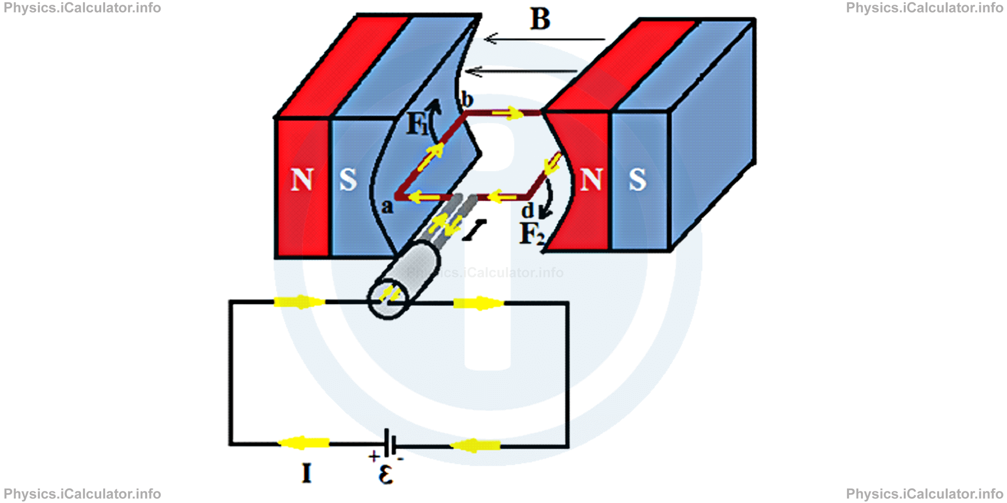
A current I flows through the loop as shown by the yellow arrows. The magnetic field lines lie from North to South poles of magnets (from right to left). Using the Fleming's Left Hand Rule (magnetic field lines punch the palm, the four fingers show the current, the thumb shows the magnetic force), we see that a torque is produced in the two lateral sides of the loop because current flows in opposite directions.
To calculate the torque on the loop we must calculate the forces acting at the lateral sides of the loop only because the front and the back sides are parallel to the magnetic field lines and therefore, they don't produce any force (sin 00 = 0, so F = I ∙ B ∙ L ∙ sin 00 = 0). Let's denote the four vertices of the loop by a, b, c and d respectively. The turning arm is therefore 'ad'/2 or 'bc'/2. If we denote by L the loop sides ab and bc in which the magnetic force produces rotation, we obtain for the scalar version of magnetic forces F1 and F2:
= I ∙ B ∙ L
and
= I ∙ B ∙ L
Therefore, the magnetic forces F1 and F2 are equal in magnitude and opposite in direction. If we denote by x/2 the distance from the lateral sides ab and bc to the rotating axis passing through the centre of loop, we obtain for the maximum torque τ produced:
= I ∙ B ∙ L ∙ x/2 + I ∙ B ∙ L ∙ x/2
= 2I ∙ B ∙ L ∙ x/2
= I ∙ B ∙ L ∙ x
where x is the width of the loop (it represents the side lengths ad or bc).
Since L ∙ x gives the area A of the loop, we can write the last equation as
Example 4
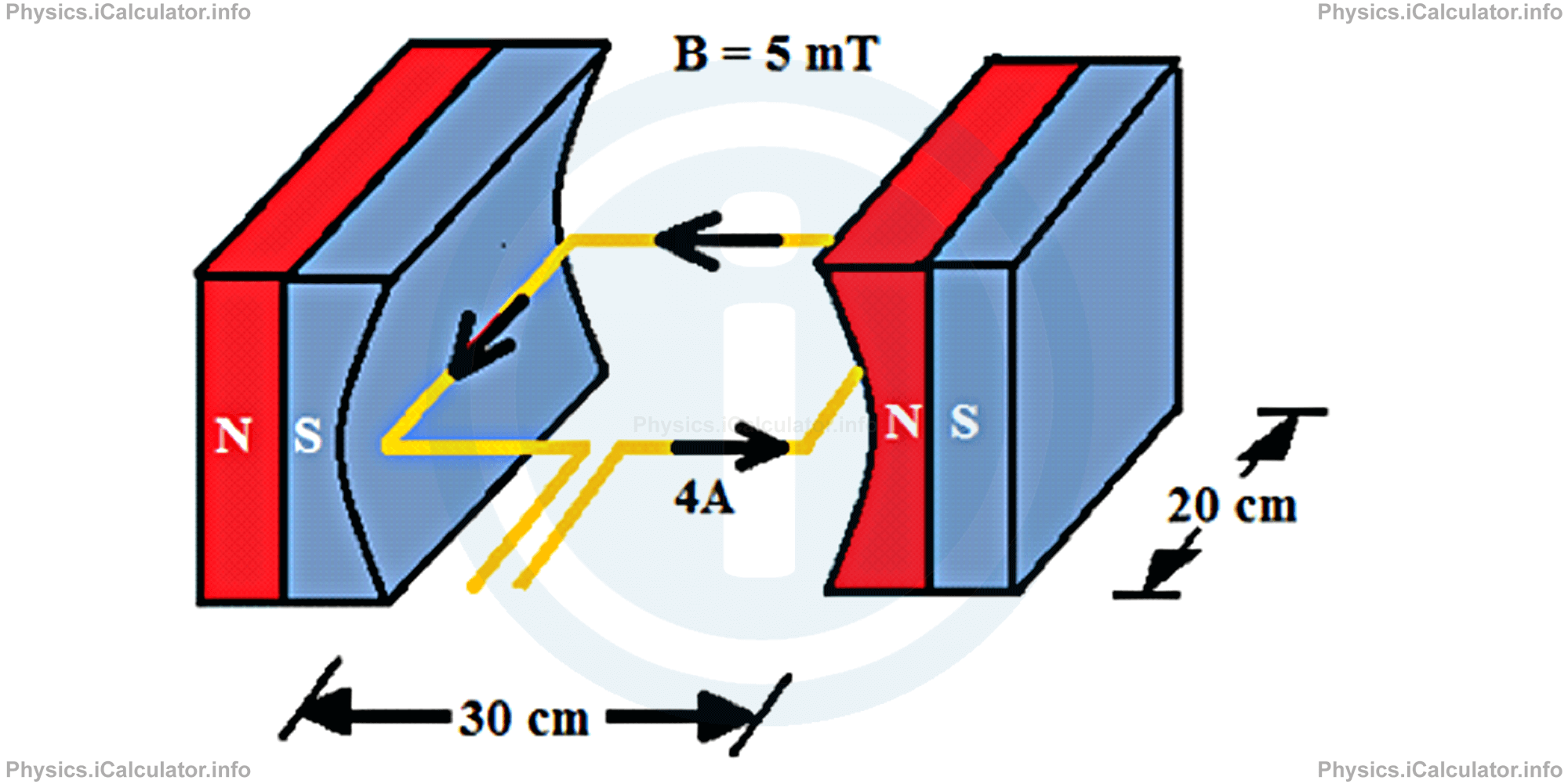
What is the maximum torque produced by the rectangular loop placed between the opposite poles of two magnets shown in the figure? The magnetic field between the opposite poles is 5mT and the current flowing through the loop is 4A. The dimensions of the loop are 30cm × 20cm. What is the turning direction of the loop?
Solution 4
Clues:
I = 4A
B = 5mT = 5 × 10⁻³ T
A = 30 cm × 20 cm = 600 cm2 = 0.06 m2 = 6 × 10⁻² m2
τmax = ?
The maximum torque produced by this system is
= (4A) ∙ (5 × 10⁻³ T) ∙ (6 × 10⁻² m2 )
= 120 × 10-5 N ∙ m
= 0.0012 N ∙ m
You have reached the end of Physics lesson 16.3.4 Magnetic Force on a Current Carrying Loop. The Motor Effect. There are 5 lessons in this physics tutorial covering Magnetic Force on a Current Carrying Wire. Ampere's Force, you can access all the lessons from this tutorial below.
More Magnetic Force on a Current Carrying Wire. Ampere's Force Lessons and Learning Resources
Whats next?
Enjoy the "Magnetic Force on a Current Carrying Loop. The Motor Effect" physics lesson? People who liked the "Magnetic Force on a Current Carrying Wire. Ampere's Force lesson found the following resources useful:
- Motor Effect Feedback. Helps other - Leave a rating for this motor effect (see below)
- Magnetism Physics tutorial: Magnetic Force on a Current Carrying Wire. Ampere's Force. Read the Magnetic Force on a Current Carrying Wire. Ampere's Force physics tutorial and build your physics knowledge of Magnetism
- Magnetism Revision Notes: Magnetic Force on a Current Carrying Wire. Ampere's Force. Print the notes so you can revise the key points covered in the physics tutorial for Magnetic Force on a Current Carrying Wire. Ampere's Force
- Magnetism Practice Questions: Magnetic Force on a Current Carrying Wire. Ampere's Force. Test and improve your knowledge of Magnetic Force on a Current Carrying Wire. Ampere's Force with example questins and answers
- Check your calculations for Magnetism questions with our excellent Magnetism calculators which contain full equations and calculations clearly displayed line by line. See the Magnetism Calculators by iCalculator™ below.
- Continuing learning magnetism - read our next physics tutorial: Magnetic Force on a Wire Moving Inside a Magnetic Field. Lorentz Force
Help others Learning Physics just like you
Please provide a rating, it takes seconds and helps us to keep this resource free for all to use
We hope you found this Physics lesson "Magnetic Force on a Current Carrying Wire. Ampere's Force" useful. If you did it would be great if you could spare the time to rate this physics lesson (simply click on the number of stars that match your assessment of this physics learning aide) and/or share on social media, this helps us identify popular tutorials and calculators and expand our free learning resources to support our users around the world have free access to expand their knowledge of physics and other disciplines.
Magnetism Calculators by iCalculator™
- Angular Frequency Of Oscillations In Rlc Circuit Calculator
- Calculating Magnetic Field Using The Amperes Law
- Capacitive Reactance Calculator
- Current In A Rl Circuit Calculator
- Displacement Current Calculator
- Electric Charge Stored In The Capacitor Of A Rlc Circuit In Damped Oscillations Calculator
- Electric Power In A Ac Circuit Calculator
- Energy Decay As A Function Of Time In Damped Oscillations Calculator
- Energy Density Of Magnetic Field Calculator
- Energy In A Lc Circuit Calculator
- Faradays Law Calculator
- Frequency Of Oscillations In A Lc Circuit Calculator
- Impedance Calculator
- Induced Emf As A Motional Emf Calculator
- Inductive Reactance Calculator
- Lorentz Force Calculator
- Magnetic Dipole Moment Calculator
- Magnetic Field At Centre Of A Current Carrying Loop Calculator
- Magnetic Field In Terms Of Electric Field Change Calculator
- Magnetic Field Inside A Long Stretched Current Carrying Wire Calculator
- Magnetic Field Inside A Solenoid Calculator
- Magnetic Field Inside A Toroid Calculator
- Magnetic Field Produced Around A Long Current Carrying Wire
- Magnetic Flux Calculator
- Magnetic Force Acting On A Moving Charge Inside A Uniform Magnetic Field Calculator
- Magnetic Force Between Two Parallel Current Carrying Wires Calculator
- Magnetic Potential Energy Stored In An Inductor Calculator
- Output Current In A Transformer Calculator
- Phase Constant In A Rlc Circuit Calculator
- Power Factor In A Rlc Circuit Calculator
- Power Induced On A Metal Bar Moving Inside A Magnetic Field Due To An Applied Force Calculator
- Radius Of Trajectory And Period Of A Charge Moving Inside A Uniform Magnetic Field Calculator
- Self Induced Emf Calculator
- Self Inductance Calculator
- Torque Produced By A Rectangular Coil Inside A Uniform Magnetic Field Calculator
- Work Done On A Magnetic Dipole Calculator