Menu
Physics Lesson 17.1.2 - Analogue and Digital Signals
Please provide a rating, it takes seconds and helps us to keep this resource free for all to use
Welcome to our Physics lesson on Analogue and Digital Signals, this is the second lesson of our suite of physics lessons covering the topic of Electronic Essentials: Analogue and Digital Signals, Binary Operations and Logic Gates, you can find links to the other lessons within this tutorial and access additional physics learning resources below this lesson.
Analogue and Digital Signals
In tutorial 16.14 "Alternating Current. LC Circuits", we have explained that the current we get from the power source (AC) is sinusoidal, i.e. it changes in a sinusoidal fashion. Likewise, sound waves can be expressed as sinusoidal waves as well. Therefore, the audio system we mentioned earlier, [i.e. normal sound → input device (microphone) → processor (amplifier) → output device (loudspeaker) → louder sound] is made entirely from sinusoidal signals, which we call analogue.
On the other hand, there are electronic systems, which operate by combining only two types of signals: HIGH and LOW (ON and OFF). These are known as digital signals. In other words, in digital systems there is a fixed number of known inputs and outputs which are combined together to give a certain result.
The difference between analogue and digital signals is shown in the figure below.
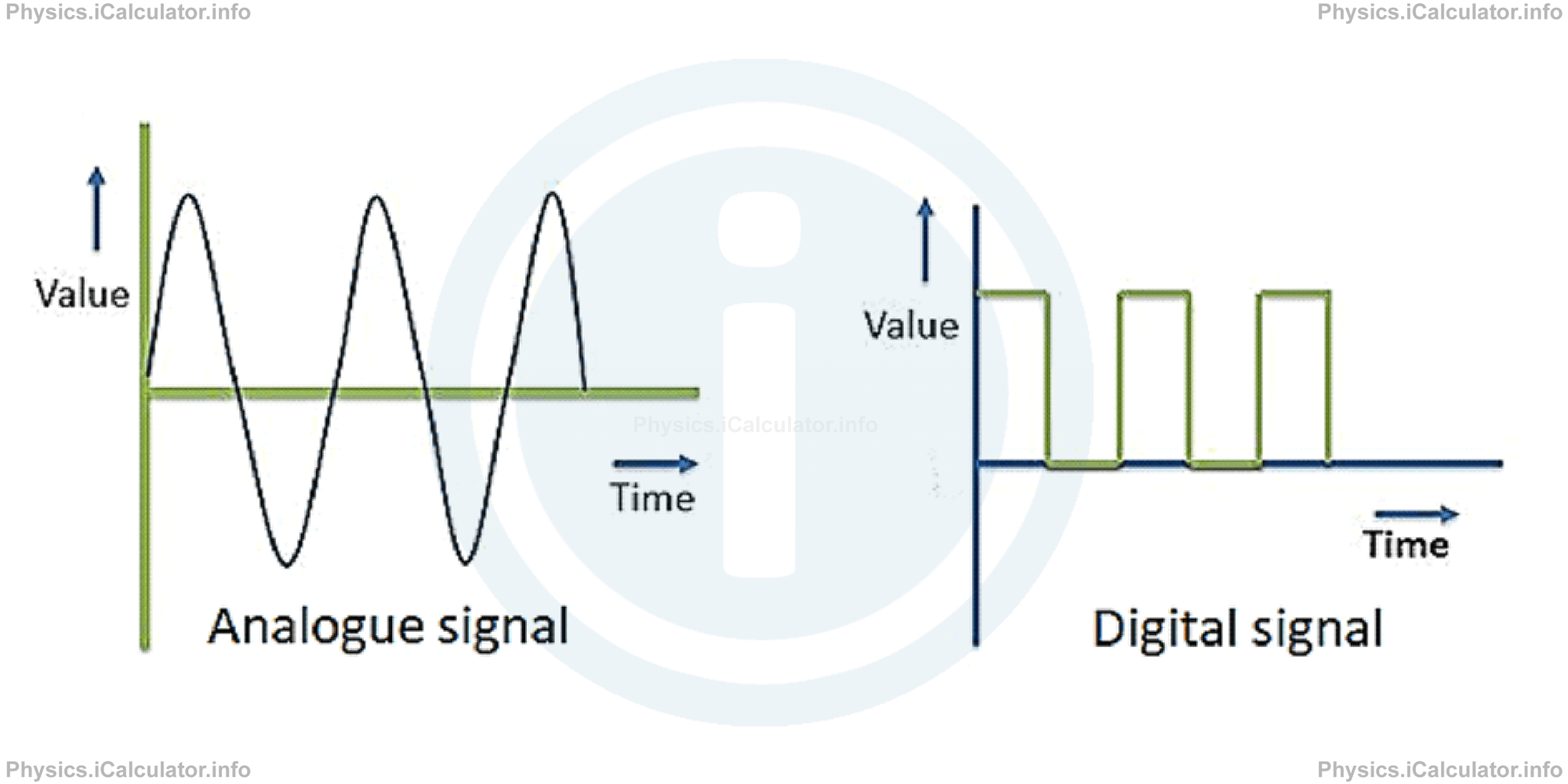
Digital signals are produced when there are only two possible input voltages: 0V (LOW) and 5V (HIGH). Symbolically, the LOW voltage is denoted as 0 and the HIGH voltage is denoted by 1. This is just for convenience, i.e. to make these values appear easier on the screen. If we consider only one of these signals (one 0 or 1), this represents a bit (binary digit).
For example, if you see on the screen the number 10110010, you may think it as the scheme below. 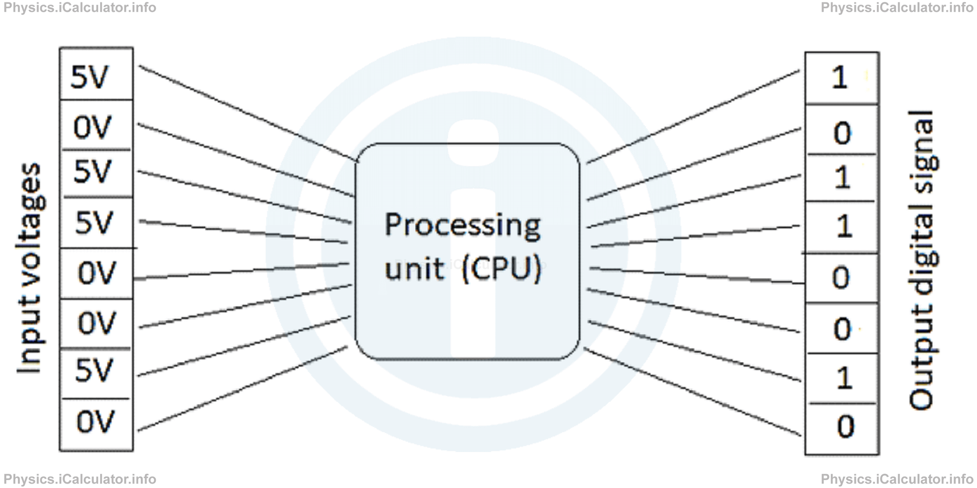
Any combination of 8 bits as in the above example, represents one Byte. In other words, 1 Byte represents the number obtained by the combination of 8 different input signals (either 0V or 5V input voltages).
You have reached the end of Physics lesson 17.1.2 Analogue and Digital Signals. There are 5 lessons in this physics tutorial covering Electronic Essentials: Analogue and Digital Signals, Binary Operations and Logic Gates, you can access all the lessons from this tutorial below.
More Electronic Essentials: Analogue and Digital Signals, Binary Operations and Logic Gates Lessons and Learning Resources
Whats next?
Enjoy the "Analogue and Digital Signals" physics lesson? People who liked the "Electronic Essentials: Analogue and Digital Signals, Binary Operations and Logic Gates lesson found the following resources useful:
- Signals Feedback. Helps other - Leave a rating for this signals (see below)
- Electronics Physics tutorial: Electronic Essentials: Analogue and Digital Signals, Binary Operations and Logic Gates. Read the Electronic Essentials: Analogue and Digital Signals, Binary Operations and Logic Gates physics tutorial and build your physics knowledge of Electronics
- Electronics Revision Notes: Electronic Essentials: Analogue and Digital Signals, Binary Operations and Logic Gates. Print the notes so you can revise the key points covered in the physics tutorial for Electronic Essentials: Analogue and Digital Signals, Binary Operations and Logic Gates
- Electronics Practice Questions: Electronic Essentials: Analogue and Digital Signals, Binary Operations and Logic Gates. Test and improve your knowledge of Electronic Essentials: Analogue and Digital Signals, Binary Operations and Logic Gates with example questins and answers
- Check your calculations for Electronics questions with our excellent Electronics calculators which contain full equations and calculations clearly displayed line by line. See the Electronics Calculators by iCalculator™ below.
- Continuing learning electronics - read our next physics tutorial: Electronic Components and Switching
Help others Learning Physics just like you
Please provide a rating, it takes seconds and helps us to keep this resource free for all to use
We hope you found this Physics lesson "Electronic Essentials: Analogue and Digital Signals, Binary Operations and Logic Gates" useful. If you did it would be great if you could spare the time to rate this physics lesson (simply click on the number of stars that match your assessment of this physics learning aide) and/or share on social media, this helps us identify popular tutorials and calculators and expand our free learning resources to support our users around the world have free access to expand their knowledge of physics and other disciplines.