Menu
Physics Lesson 17.1.5 - Boolean Algebra. Logic Gates
Please provide a rating, it takes seconds and helps us to keep this resource free for all to use
Welcome to our Physics lesson on Boolean Algebra. Logic Gates, this is the fifth lesson of our suite of physics lessons covering the topic of Electronic Essentials: Analogue and Digital Signals, Binary Operations and Logic Gates, you can find links to the other lessons within this tutorial and access additional physics learning resources below this lesson.
Boolean Algebra. Logic Gates
The English mathematician George Boole introduced several relationships between the mathematical quantities that contain only two values: either True or False, which as explained earlier, can also be denoted by a 1 or 0 respectively. This system was later given the name "Boolean Algebra". The results of all mathematical operations performed on these values can also possess only two values: 1 or 0.
Logic gates are small electronic devices. They contain two inputs and a single output which perform a Boolean function. Obviously, all data in logic gates are binary digits.
The seven basic operations of Boolean Algebra are: AND, OR, NOT, NAND, NOR, XOR and XNOR. We will explain below the logic of each of these operations.
1: AND operation
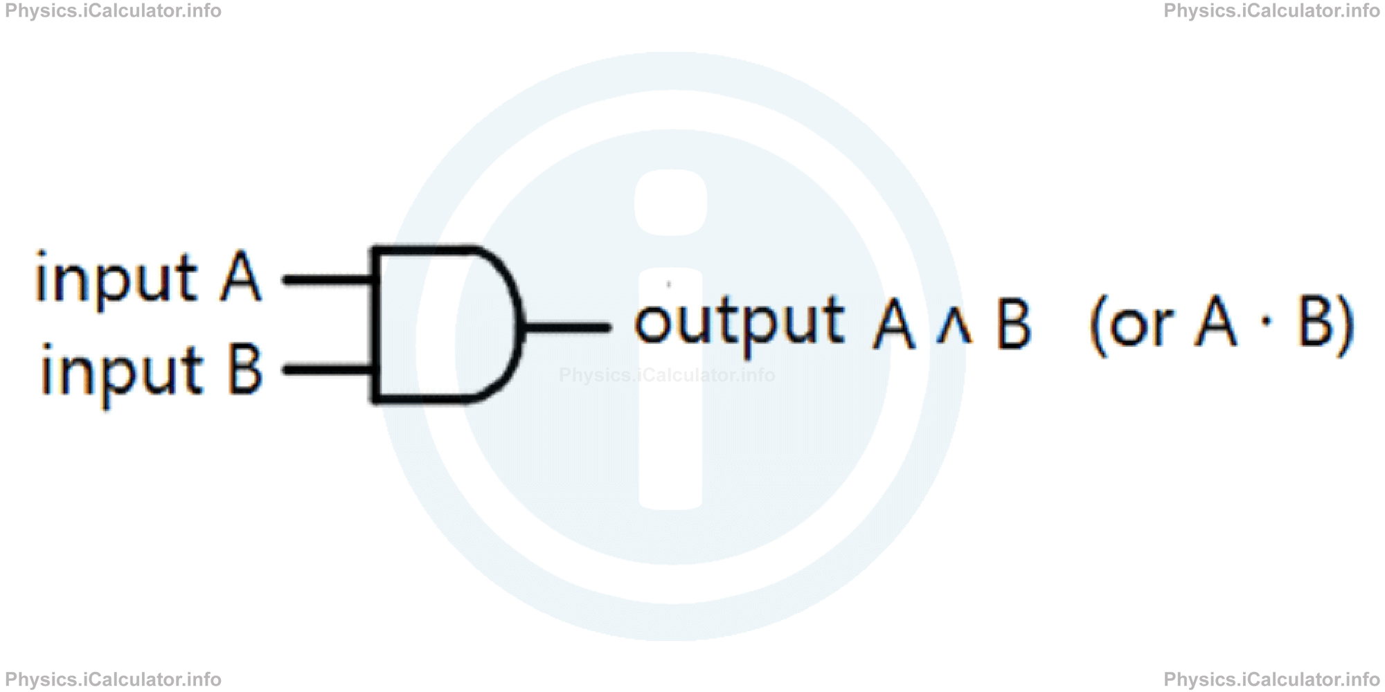
This operation gives TRUE (otherwise known as HIGH or 1) as an output when all inputs are TRUE (otherwise known as HIGH or 1). This operation is similar to intersection of sets in the set theory in mathematics, in which an element belongs to the intersection set only if it is an element of each individual set. Recall that sometimes the intersection of set is also represented through the multiplication symbol ( · ).
The AND operation is represented by the symbol ( ˄ ) and in electronic diagrams is shown by:
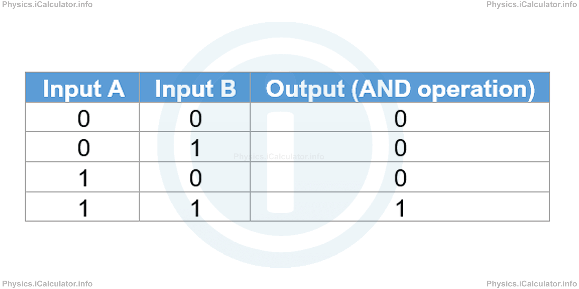
The following truth table gives the relationship between inputs and output for the AND logic operation.
2: OR operation
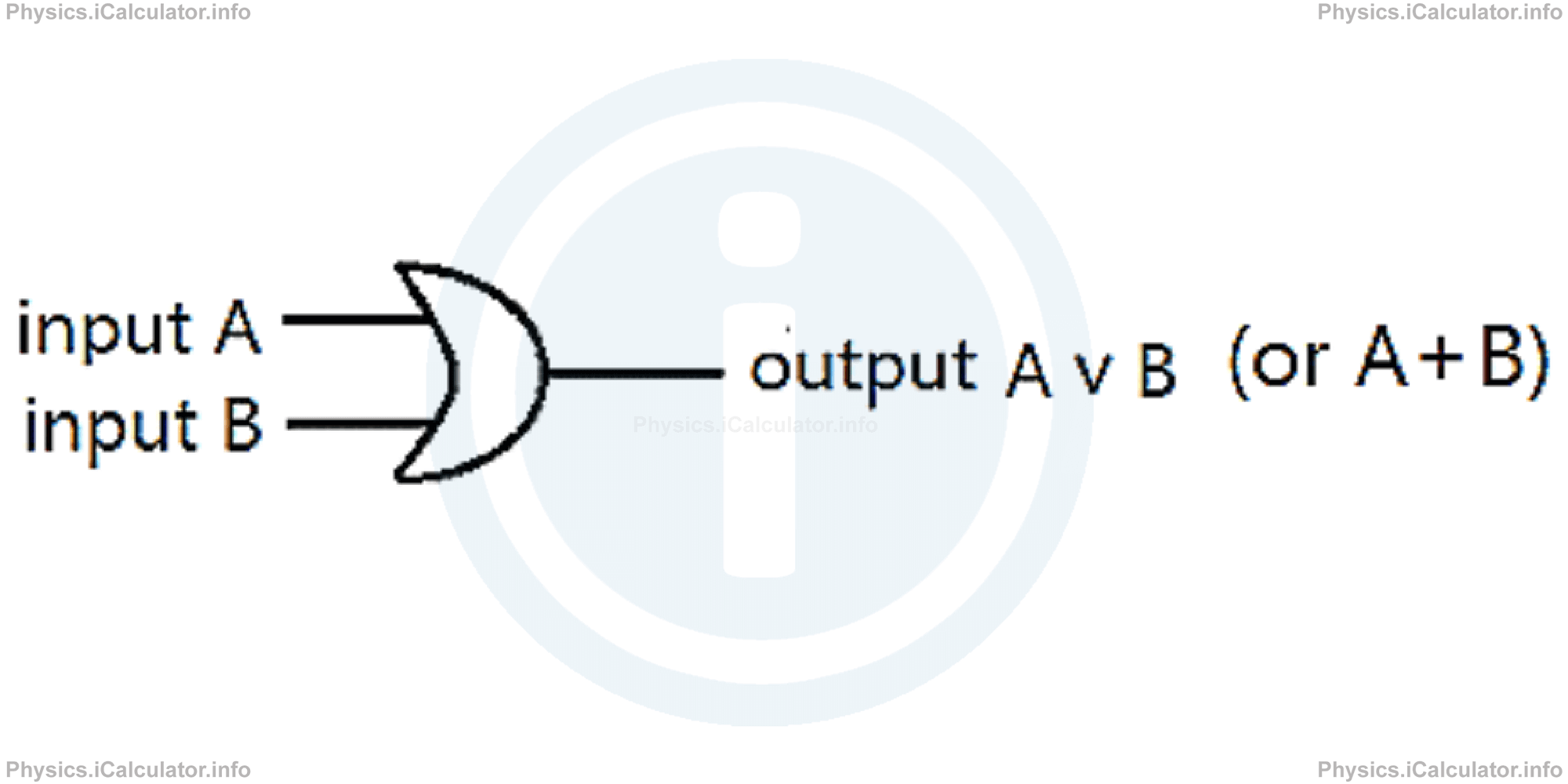
This operation gives TRUE (otherwise known as HIGH or 1) as an output when at least one of inputs is TRUE (otherwise known as HIGH or 1). This operation is similar to union of sets in the set theory in mathematics, in which an element belongs to the union set if it is an element of either of individual sets. Recall that sometimes the intersection of set is also represented through the addition symbol ( + ).
The OR operation is represented by the symbol ( ˅ ) and in electronic diagrams is shown by:
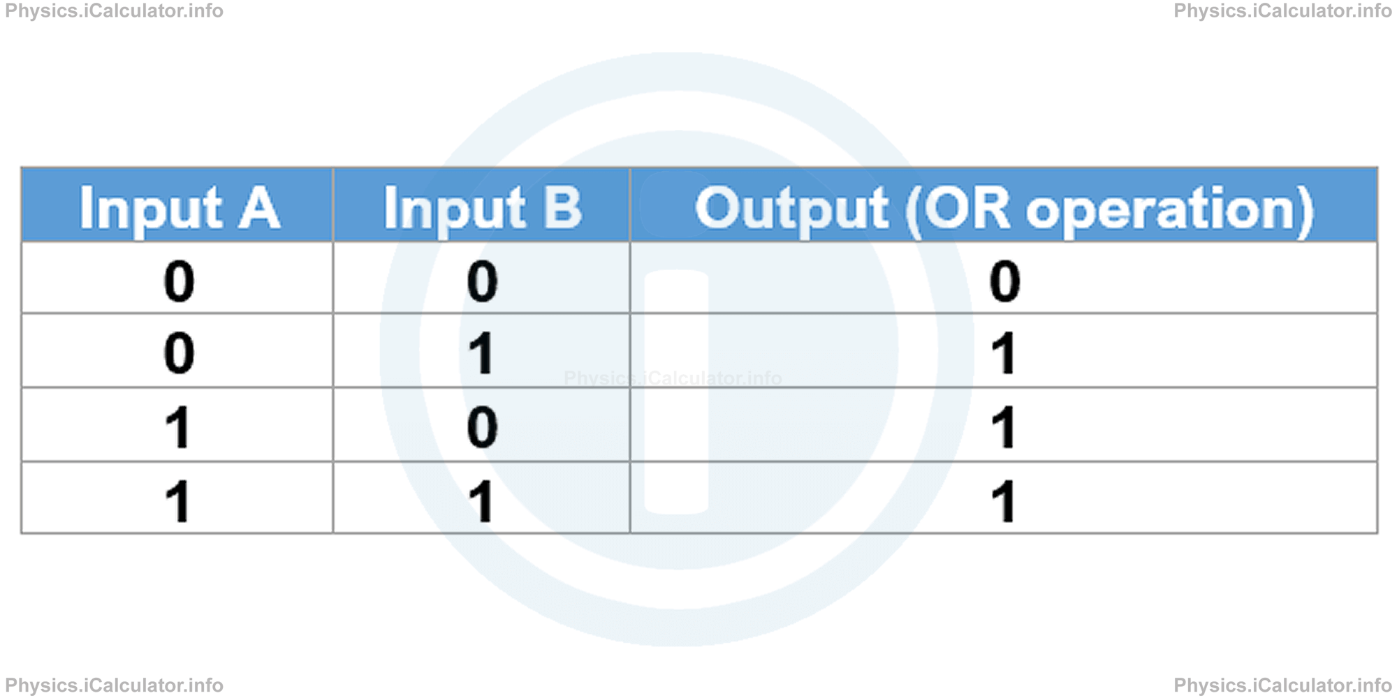
The following truth table gives the relationship between inputs and output for the OR logic operation.
Example 2
Draw a logic diagram for:
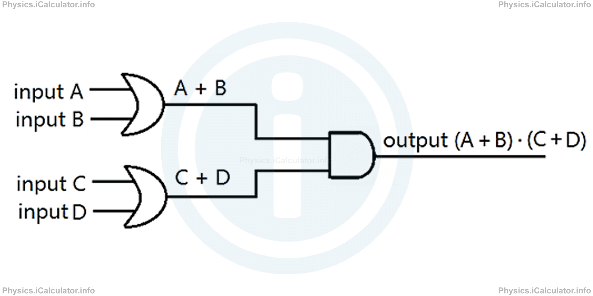
- (A + B) · (C + D)
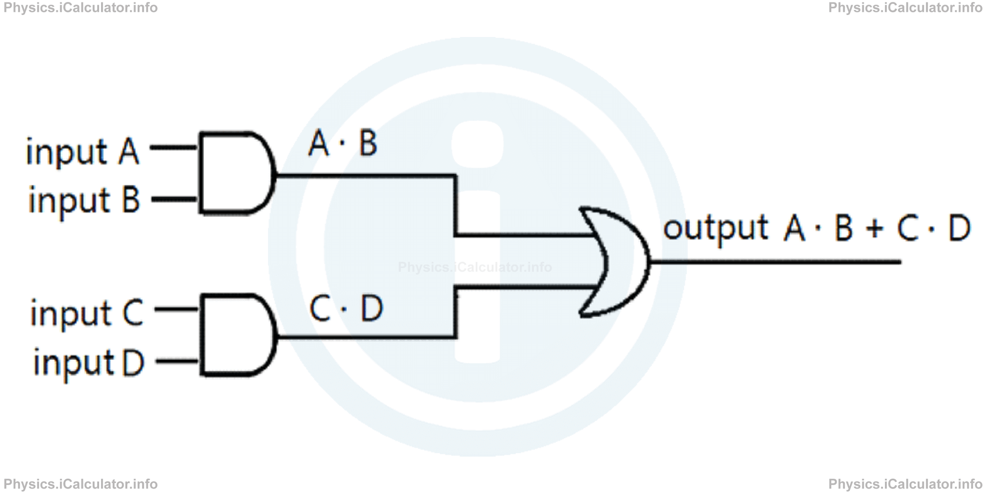
- A · B + C · D
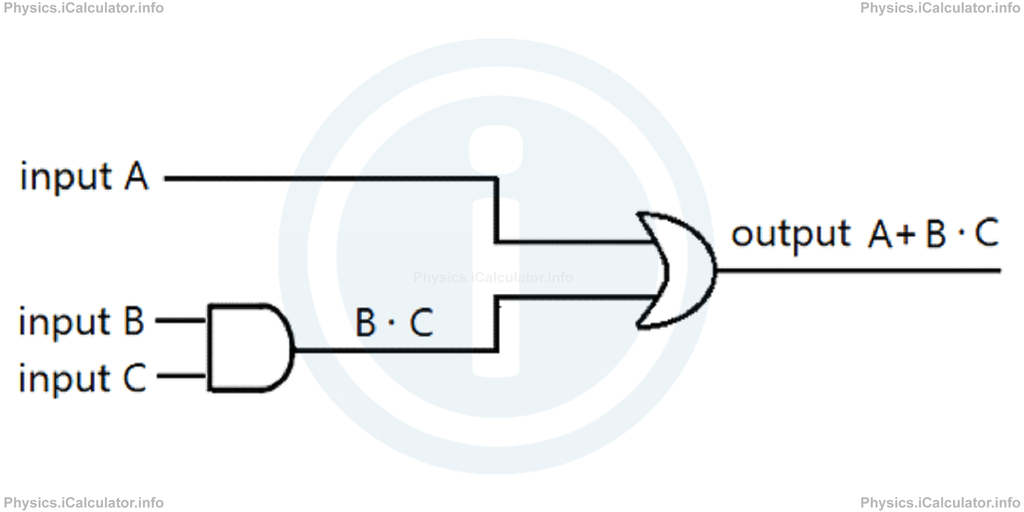
- A + B · C
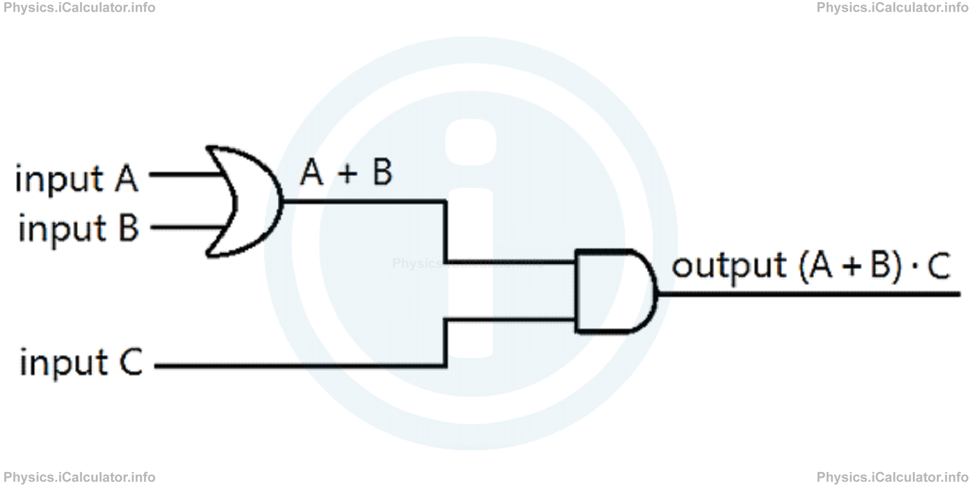
- (A + B) · C
Solution 2
- The symbol ( · ) stands for AND and the symbol ( + ) for the OR operation. Thus, we have:
- In this case, the results of two AND operations form an OR one. Thus, we obtain:
- Here we have only three inputs, A , B and C, where the output of AND operation of inputs A and B forms an OR operation with the input C. Hence, we obtain the following diagram:
- In this case, the output of the OR operation of inputs A and B forms an AND operation with the input C. Hence, we obtain the following diagram:
3: NOT operation
This is a logic operation that inverts the value of input. This means when the input is 1 the output is 0 and when the input is 0 the output is 1.
The NOT operation is shown symbolically through a horizontal line above the input letter (the negation symbol). The symbol used in schematic diagrams for the NOT operation is shown below:
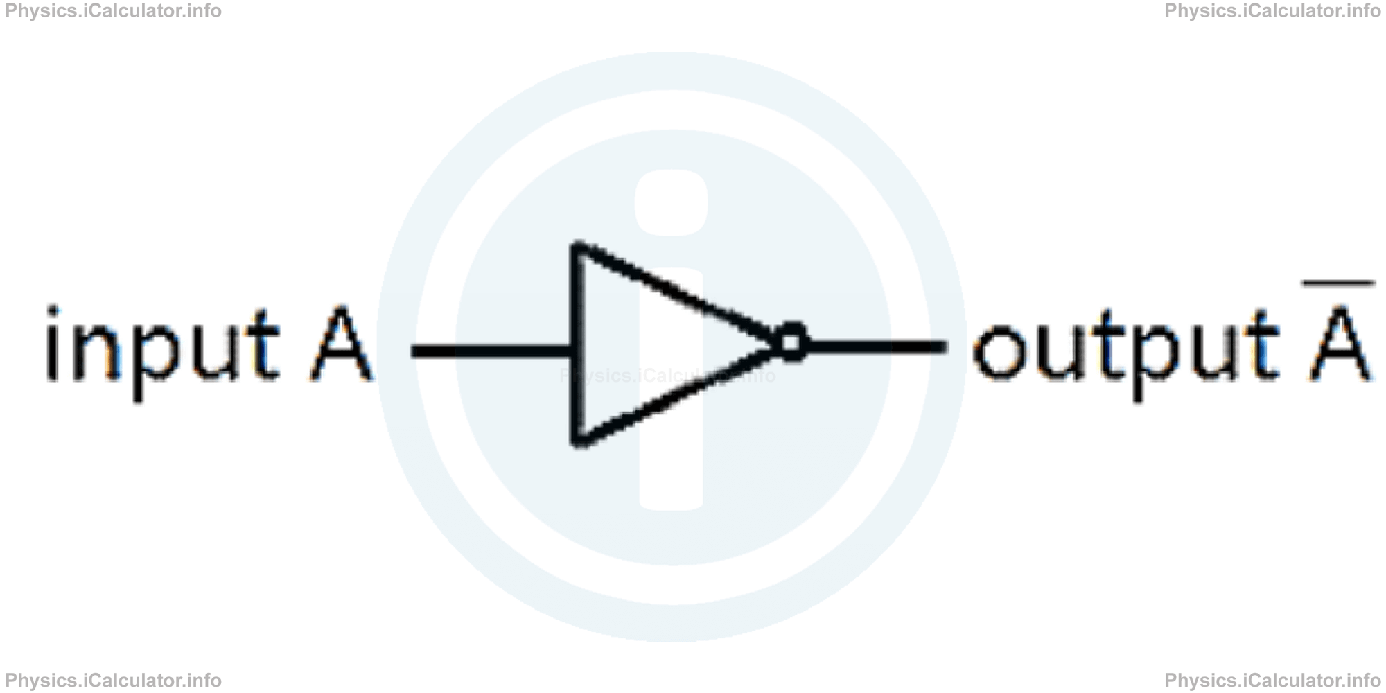
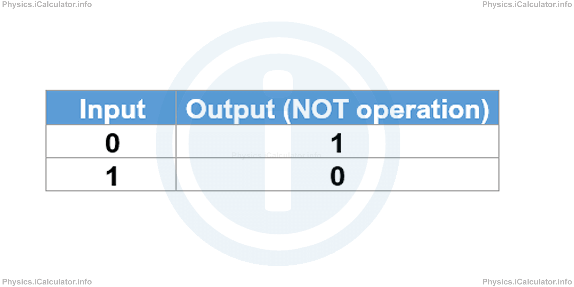
The NOT operation does not require necessarily the presence of two inputs. One input is enough to reverse the result of the corresponding output. The truth table for NOT operation is:
Example 3
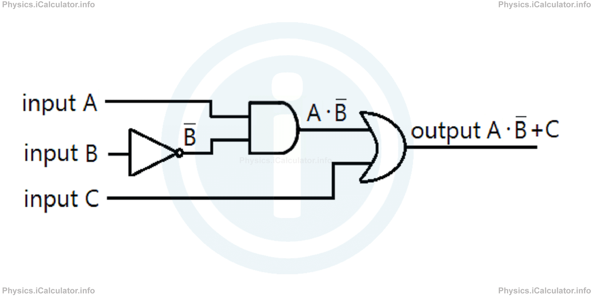
Draw a logic diagram for A ∙ B + C
Solution 3
The input of B is first reversed through the NOT operation. Then, it forms an AND operation with the input A. The output of this operation forms an OR operation with the input C.
Thus, we obtain the following diagram:
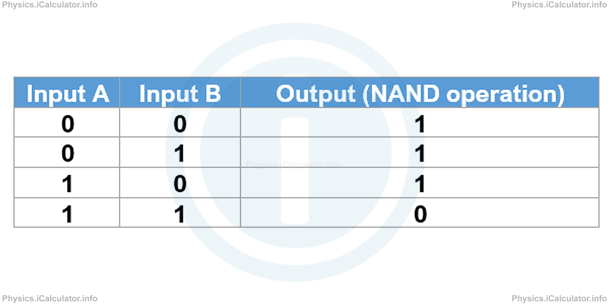
4: NAND operation
NAND is an abbreviation for NOT AND. Thus, a NAND logic operation reverses the output of the corresponding AND. It is represented mathematically through the symbol A∧B or simply A∙B, while in circuit diagrams the NAND operation is represented through the symbol shown in the figure below:
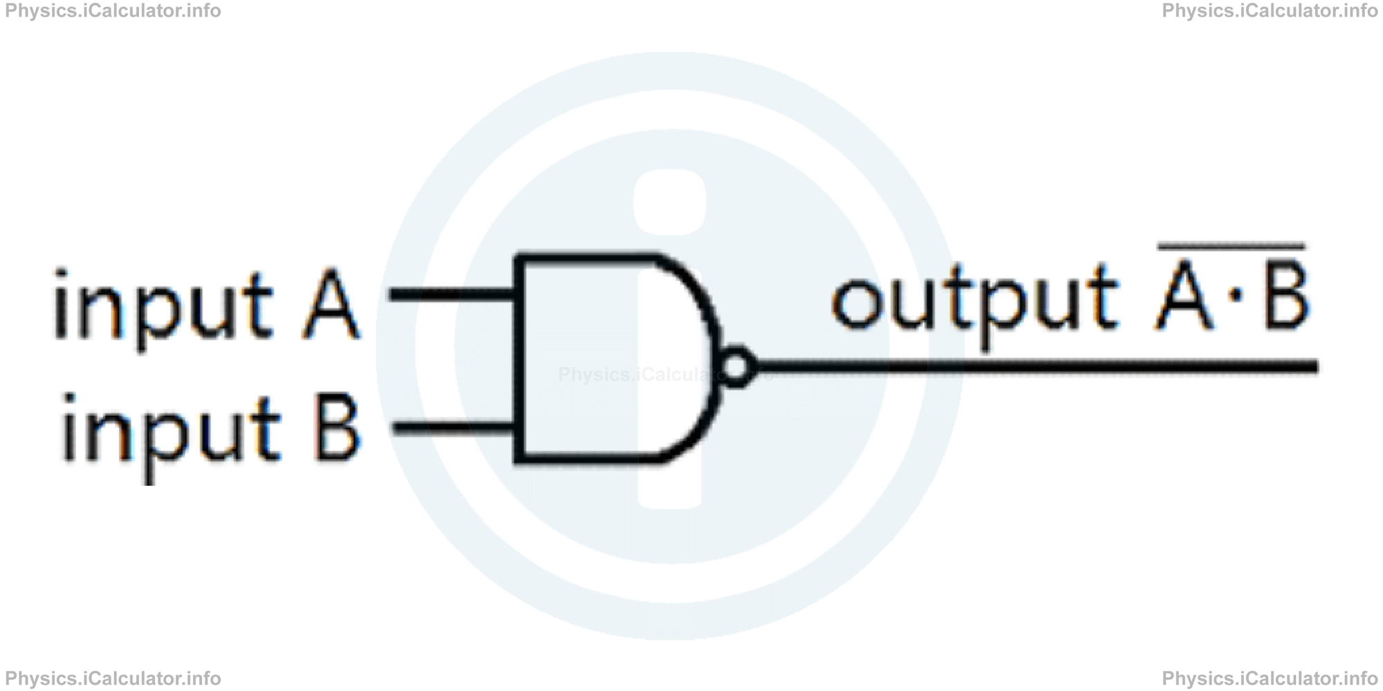
The truth table for NAND logic operation is:
Example 4
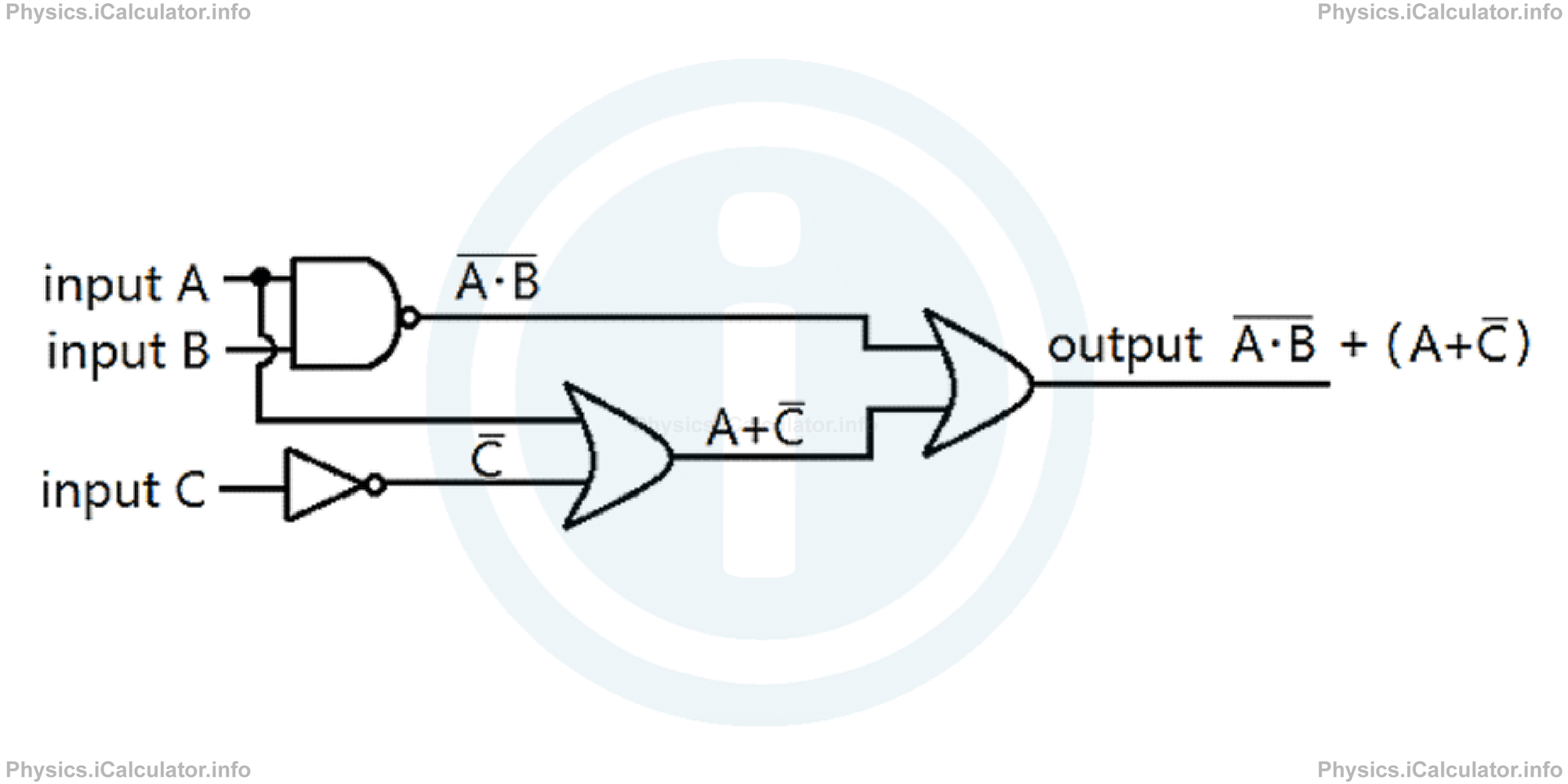
- Draw a logic diagram for A · B + A + C
- What is the output signal if all inputs are HIGH (or 1)?
Solution 4
- The output of NAND logic operation for the inputs A and B forms an OR logic operation with the output of OR operation between the input A and the NOT input C. Thus, we obtain the following diagram:
- If all inputs are 1, then A · B = 1. This means the corresponding NAND operation is A ∙ B= 0.
On the other hand, since input C = 1, the corresponding NOT operation is C = 0. Thus, A + C = 1 because this is an OR logic operation which gives 1 when at least one input is 1 (here we have input A = 1).
Therefore, the output of this logic expression is 1 as there is another OR operation between the two above outputs where the first is 0 and the second is 1. This means the output signal gives HIGH.
5: NOR operation
NOR is an abbreviation for NOT OR. Thus, a NOR logic operation reverses the output of the corresponding OR. It is represented mathematically through the symbol A ∨ B or simply A + B, while in circuit diagrams the NOR operation is represented through the symbol shown in the figure below:
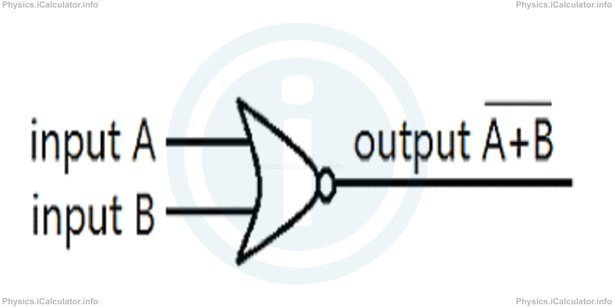
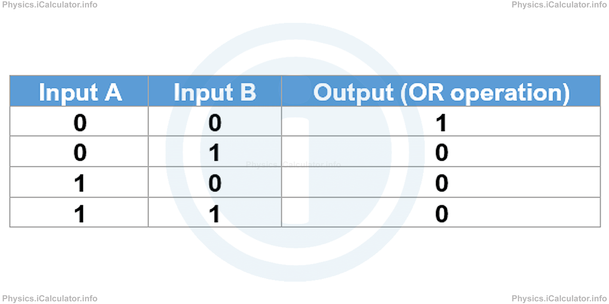
The truth table for the NOR logic operation is:
Example 5
- Draw a logic diagram for A + B + B · C
- What is the output signal if all inputs are LOW (or 0)?
Solution 5
- The operation A + B is a NOR logic operation while the operation of B and C is an OR type. But first, the input of C must be reversed (C means NOT C).
On the other hand, the two above outputs are connected through an OR logic operation. Therefore, we obtain the following diagram: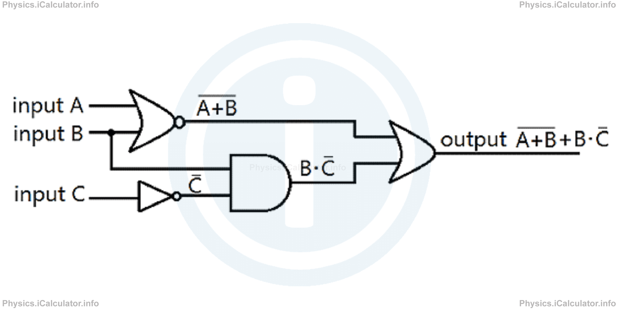
- Since the inputs A and B are both 0, the OR operation A + B is 0 as well. Therefore, the corresponding NOR operation A + B gives 1.
On the other hand, since the input C is 0, the corresponding NOT operation C is 1. Therefore, the OR operation B · C is 0 · 1 = 0.
Finally, the output of the OR operation A + B + B · C is:
= 1 + 0
= 1
Therefore, the output signal is HIGH (or 1).
6: XOR operation
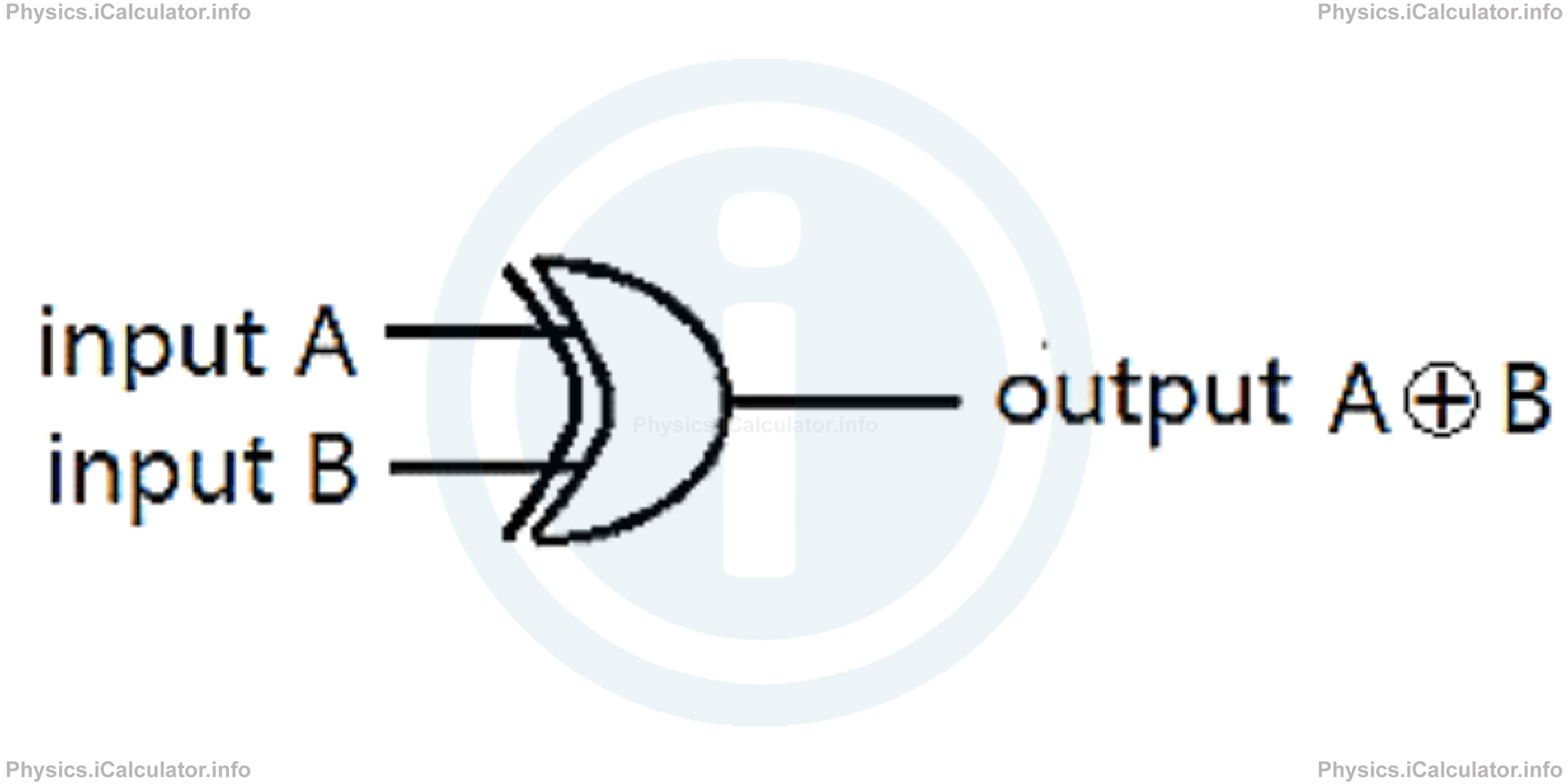
XOR is an abbreviation for EXCLUSIVE OR. It gives HIGH (or 1) when both inputs are the same (both 0 or both 1) and it gives LOW (or 0) when the two inputs are different. The mathematical symbol of XOR logic operation is ⨁ and the corresponding logic gate in a circuit diagram is shown as:
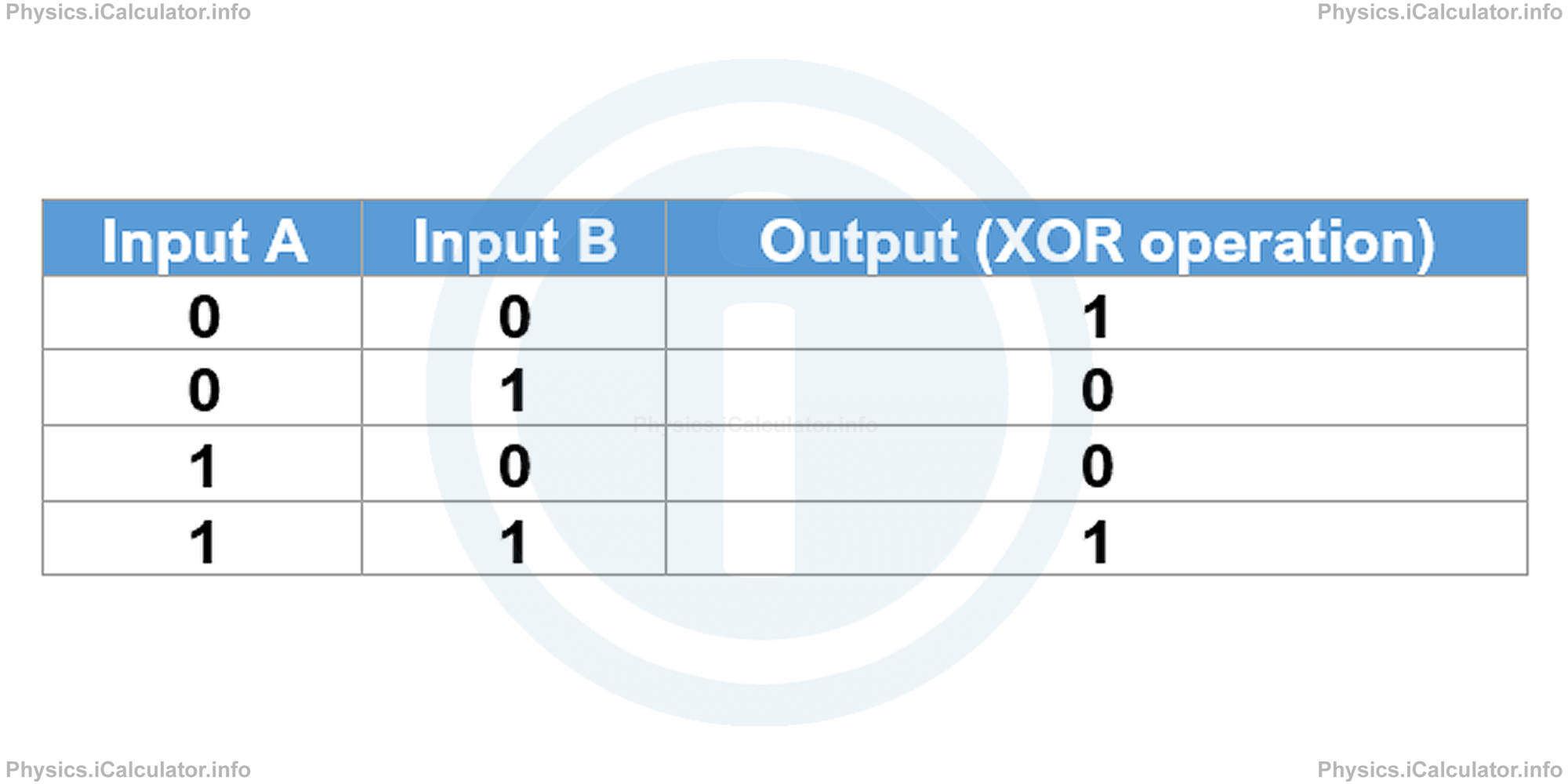
The truth table for the XOR logic operation is:
Example 6
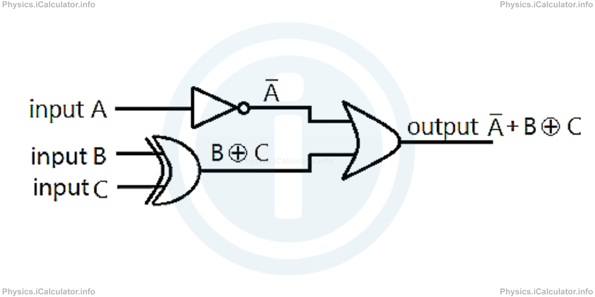
- Draw a logic diagram for A + (B ⨁ C)
- Find the value of output if input A = 1, input B = 0 and input C = 1.
Solution 6
- The inputs B and C are connected to each other through the XOR logic operation. Their output forms an OR logic operation to the NOT gate of input A. Hence, we obtain:
- Since input A = 1, then A = 0 because this is a NOT operation. On the other hand, since input B = 0 and input C = 1, the corresponding XOR operation gives 0 (see the truth table above). Therefore, we have two new 0 inputs which are connected via an OR operation. From the truth table of OR logic operation, it is clear that the result (output) of this operation gives 0 as well (no signal).
7: XNOR operation
XNOR is an abbreviation for EXCLUSIVE NOR (EXCLUSIVE NOT OR). In this logic operation, there is an inversion on the NOR gate to get the XNOR gate. The output is just opposite to that of the XOR gate. If any of the inputs is high (1) excluding the condition of both, the output is low or 0.
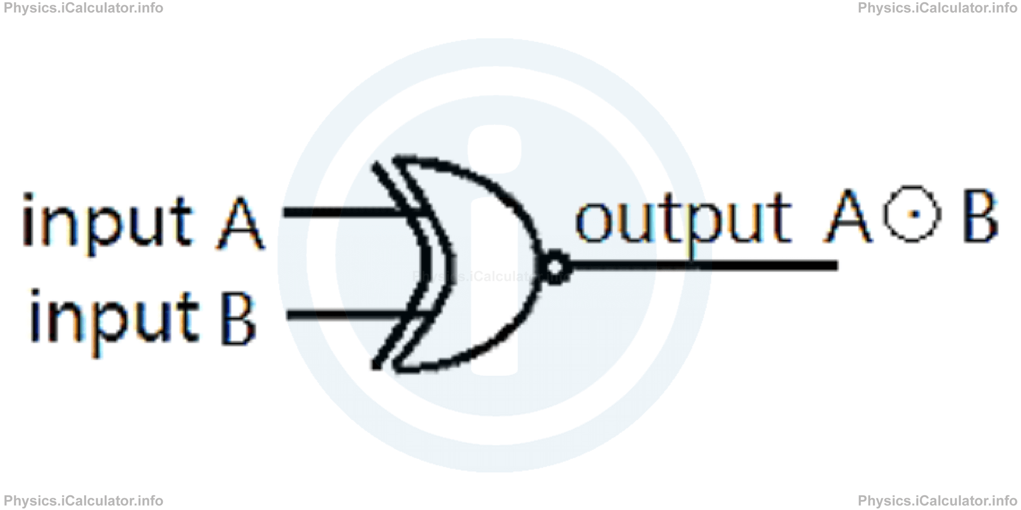
The mathematical symbol that expresses the XNOR logic operation is ⨀. This logic operation is shown in circuit diagrams by the following symbol:
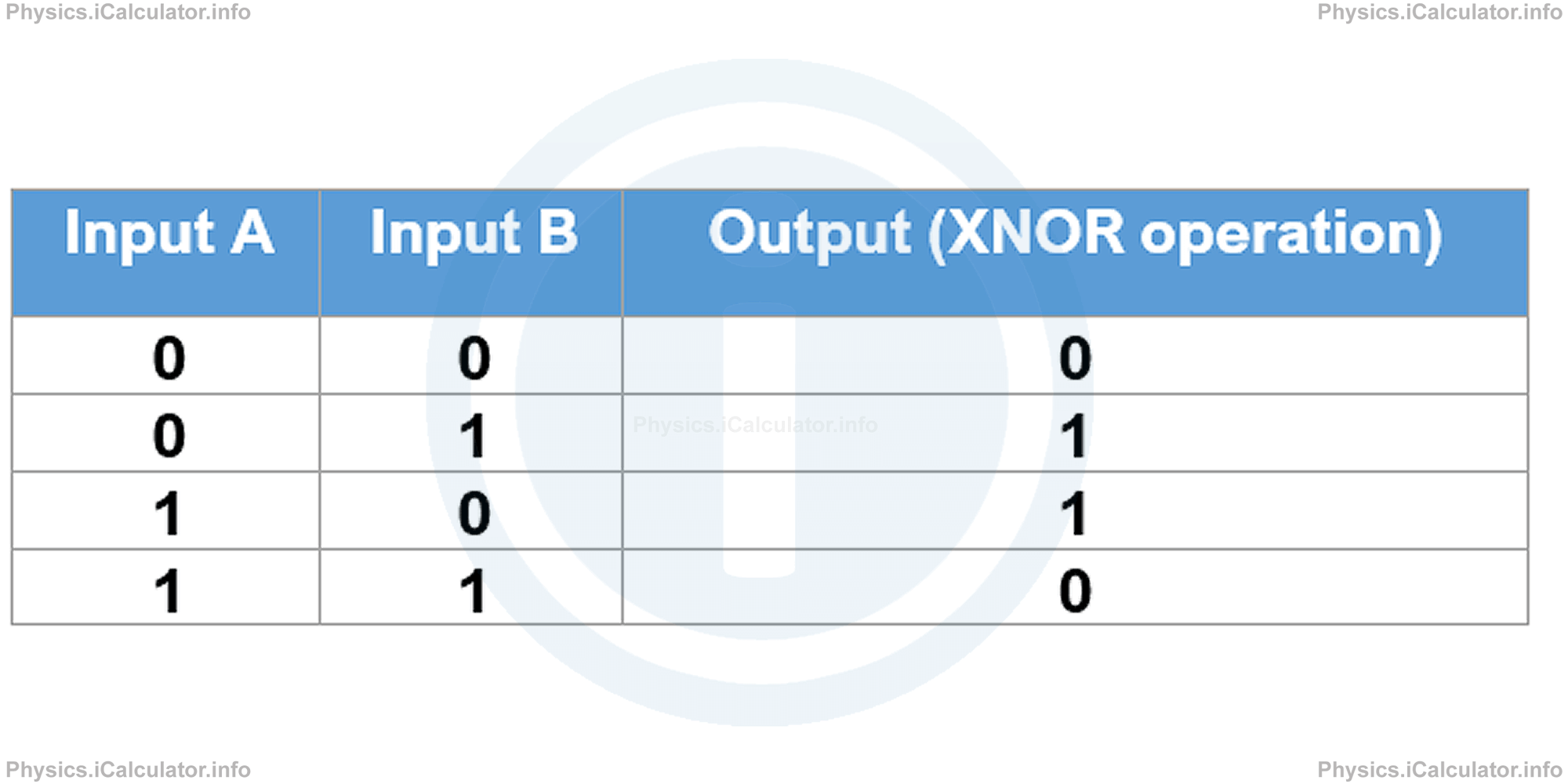
The truth table for the XNOR logic operation is:
Example 7
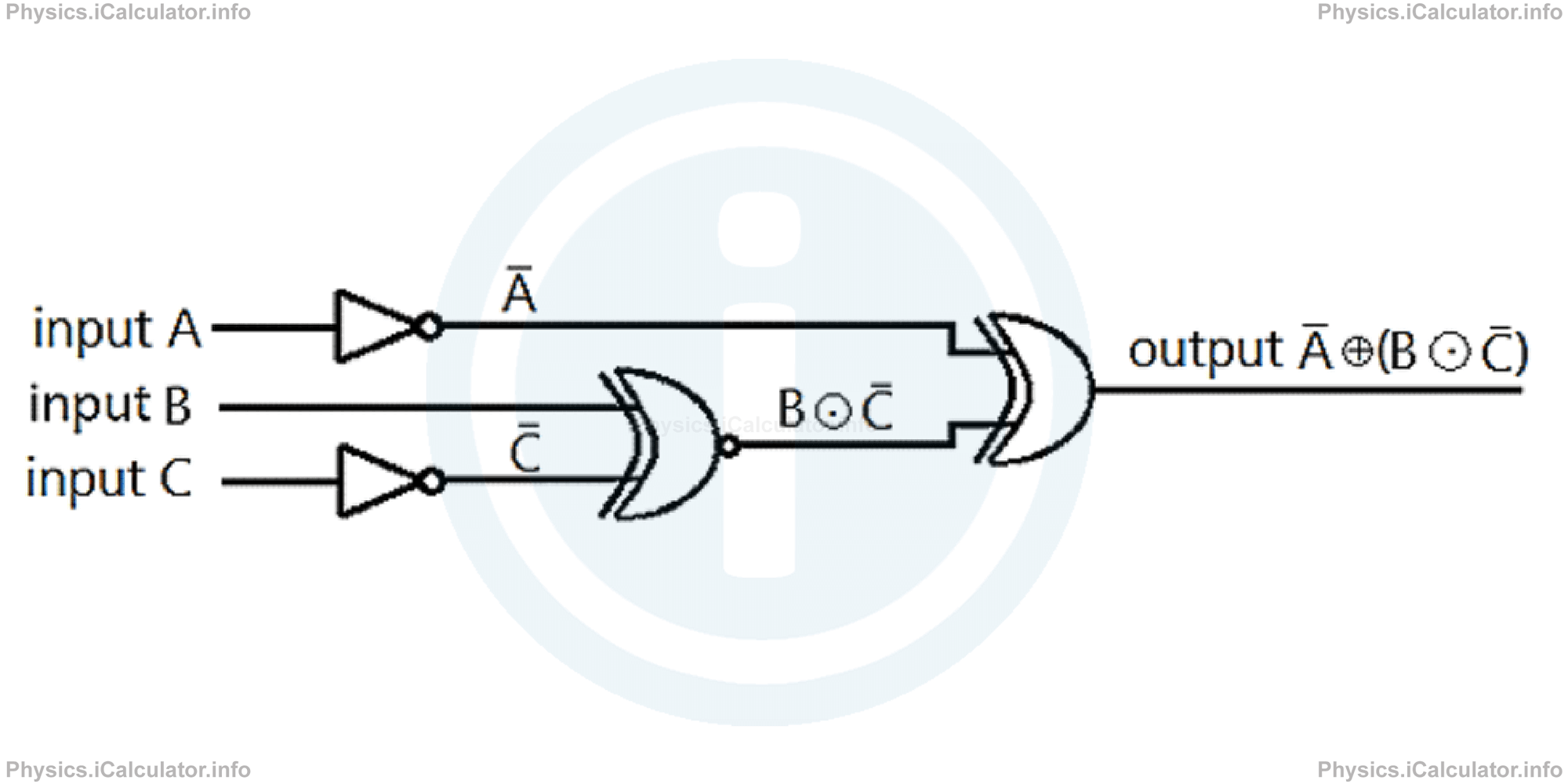
- Draw a logic diagram for A ⊕ (B ⊙ C)
- Find the output if all inputs are HIGH (or 1).
Solution 7
- The XNOR logic operation between input B and the inverse (NOT) of the input C forms a XOR logical operation to the inverse (NOT) of the input A. Hence, we obtain the following diagram:
- If the inputs A, B and C are all 1, then A = 0 and C = 0. The XNOR logic operation B ⊙ C therefore gives 1 because the inputs are different.
Therefore, the XOR operation between A and B ⊙ C gives 0 because one of inputs is 0 and the other is 1. Hence, the output is 0.
You have reached the end of Physics lesson 17.1.5 Boolean Algebra. Logic Gates. There are 5 lessons in this physics tutorial covering Electronic Essentials: Analogue and Digital Signals, Binary Operations and Logic Gates, you can access all the lessons from this tutorial below.
More Electronic Essentials: Analogue and Digital Signals, Binary Operations and Logic Gates Lessons and Learning Resources
Whats next?
Enjoy the "Boolean Algebra. Logic Gates" physics lesson? People who liked the "Electronic Essentials: Analogue and Digital Signals, Binary Operations and Logic Gates lesson found the following resources useful:
- Logic Feedback. Helps other - Leave a rating for this logic (see below)
- Electronics Physics tutorial: Electronic Essentials: Analogue and Digital Signals, Binary Operations and Logic Gates. Read the Electronic Essentials: Analogue and Digital Signals, Binary Operations and Logic Gates physics tutorial and build your physics knowledge of Electronics
- Electronics Revision Notes: Electronic Essentials: Analogue and Digital Signals, Binary Operations and Logic Gates. Print the notes so you can revise the key points covered in the physics tutorial for Electronic Essentials: Analogue and Digital Signals, Binary Operations and Logic Gates
- Electronics Practice Questions: Electronic Essentials: Analogue and Digital Signals, Binary Operations and Logic Gates. Test and improve your knowledge of Electronic Essentials: Analogue and Digital Signals, Binary Operations and Logic Gates with example questins and answers
- Check your calculations for Electronics questions with our excellent Electronics calculators which contain full equations and calculations clearly displayed line by line. See the Electronics Calculators by iCalculator™ below.
- Continuing learning electronics - read our next physics tutorial: Electronic Components and Switching
Help others Learning Physics just like you
Please provide a rating, it takes seconds and helps us to keep this resource free for all to use
We hope you found this Physics lesson "Electronic Essentials: Analogue and Digital Signals, Binary Operations and Logic Gates" useful. If you did it would be great if you could spare the time to rate this physics lesson (simply click on the number of stars that match your assessment of this physics learning aide) and/or share on social media, this helps us identify popular tutorials and calculators and expand our free learning resources to support our users around the world have free access to expand their knowledge of physics and other disciplines.