Menu
Physics Lesson 15.8.1 - Measurement of Current and Voltage
Please provide a rating, it takes seconds and helps us to keep this resource free for all to use
Welcome to our Physics lesson on Measurement of Current and Voltage, this is the first lesson of our suite of physics lessons covering the topic of Miscellaneous, you can find links to the other lessons within this tutorial and access additional physics learning resources below this lesson.
Measurement of Current and Voltage
In tutorial 15.4 "Electric Circuits. Series and Parallel Circuits. Short Circuits" we have shortly explained what ammeter and voltmeter are used for. Thus, we have explained that ammeter is used to measure the value of electric current in the circuit. It is connected in series with the operating appliance in the circuit. On the other hand, a voltmeter is used to measure the value of potential difference in the circuit. It is connected in parallel to the operating appliance in the circuit.
But why this is so? Why ammeter is connected in series to appliances and voltmeter is parallel to them? Let's explain the logic of this setup.
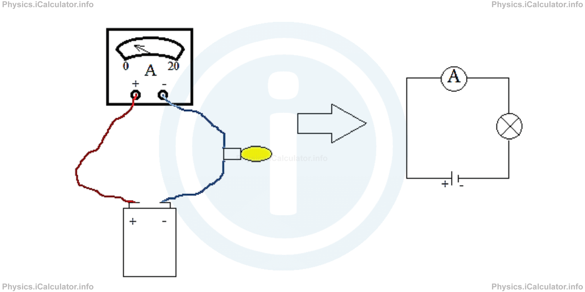
a. Ammeter
Since ammeter is used to measure the current in the circuit, it can be placed at any position of the conductor since the current is the same at every point of a circuit branch. An ammeter has a very low internal resistance because and therefore, the potential difference across its terminals is negligible, otherwise this (a high resistance) would affect the value of potential difference in the operating device. This would result in wrong values not only for the potential difference but also for electric power, efficiency and so on.
The figure below shows the connection of an ammeter in a circuit in both real and simplified view (in symbols).
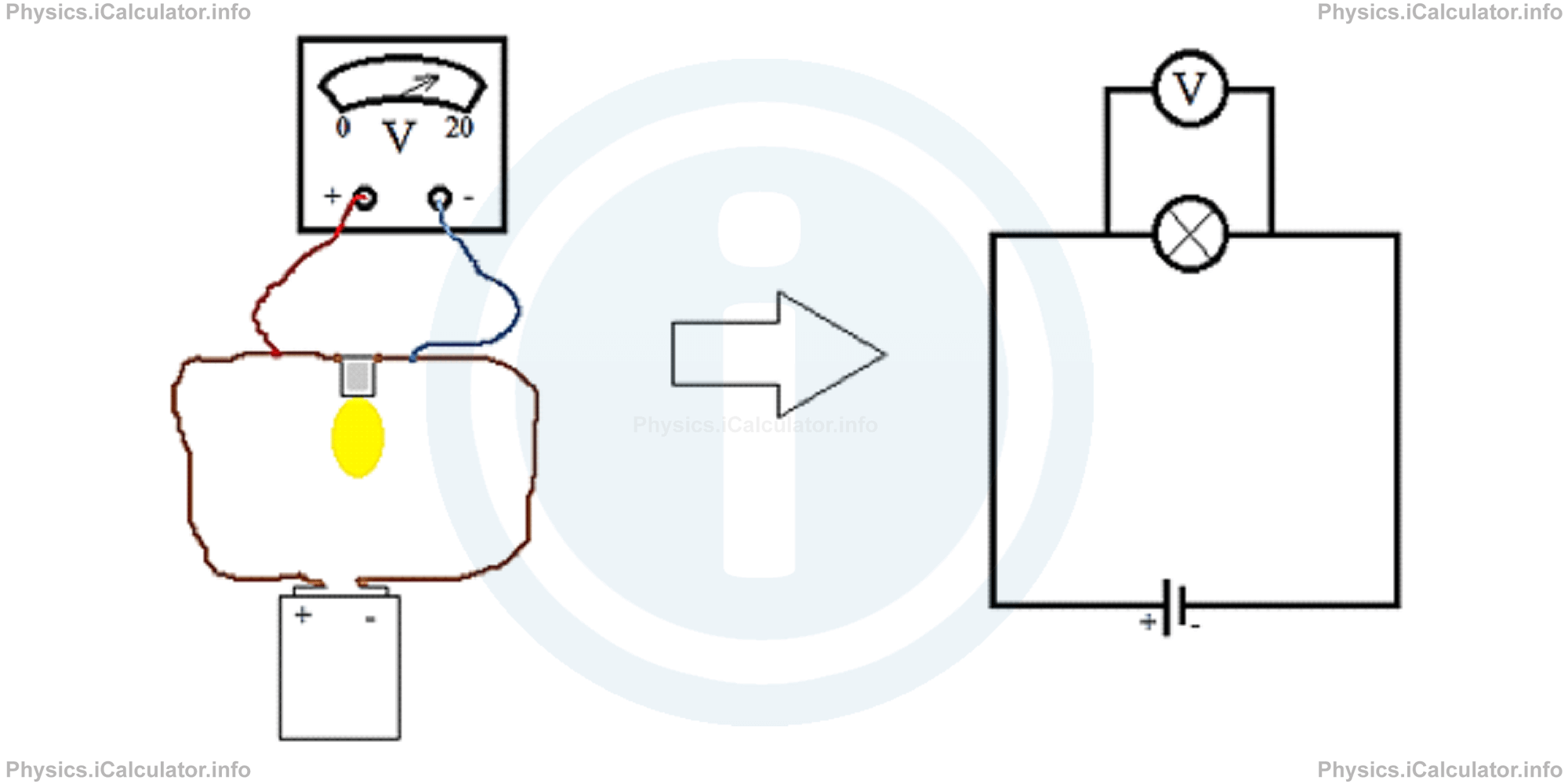
b. Voltmeter
Since voltmeter is used to measure the potential difference across the terminals of a circuit element, it must be connected in parallel to it that is one wire of voltmeter is connected before the appliance and the other wire after the appliance. This is because the voltmeter has a very high resistance in order to affect as less as possible the value of current flowing in the circuit. In other words, a very high resistance allows only a negligible amount of current to flow through the voltmeter. Look at the figure.
Example 1
What are the readings of ammeter and voltmeter in the circuit below if the resistance of battery is 1 Ω and that of the conducting wire is 0.5 Ω?
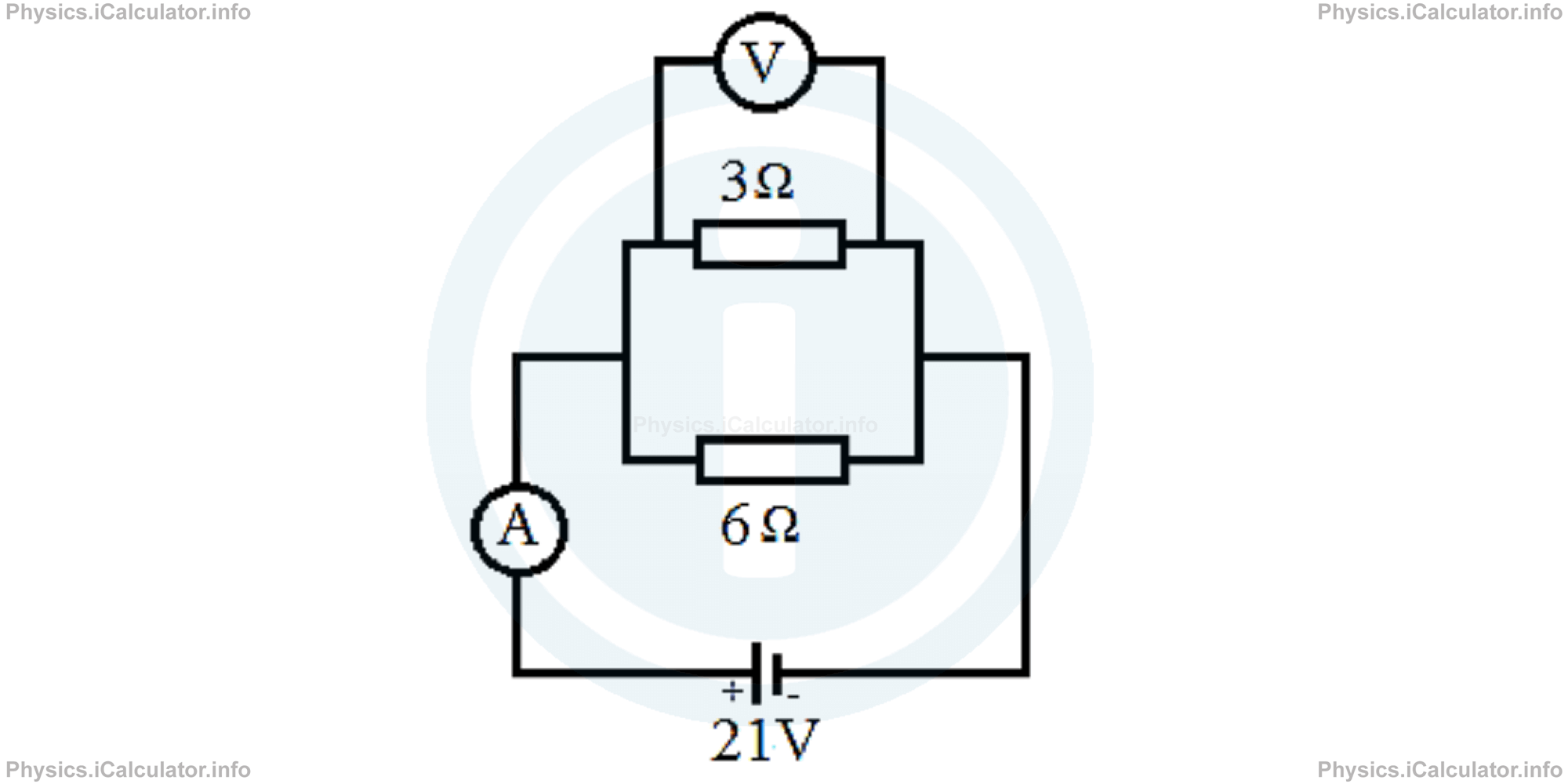
Solution 1
The ammeter measures the current in the main branch (Itot) while the voltmeter measures the potential difference ΔV in the parallel branch.
First, we must calculate the equivalent resistance in the parallel branch. We have
= 1/2 + 1/6
= 2 + 1/6
= 3/6
= 1/2
Thus, Req = 2 Ω.
The total resistance in the circuit is
= 2Ω + 0.5Ω + 1Ω
= 3.5Ω
The reading of ammeter that shows the current in the main branch therefore is
= 21 V/3.5 Ω
= 6 A
As for the reading of voltmeter, it shows the potential difference ΔV in the parallel branch, which is calculated by
= 21V - 6A ∙ 0.5Ω - 6A ∙ 1Ω
= 21V - 3V - 6V
= 12V
Therefore, the ammeter reads 6A and the voltmeter reads 12V.
You have reached the end of Physics lesson 15.8.1 Measurement of Current and Voltage. There are 5 lessons in this physics tutorial covering Miscellaneous, you can access all the lessons from this tutorial below.
More Miscellaneous Lessons and Learning Resources
Whats next?
Enjoy the "Measurement of Current and Voltage" physics lesson? People who liked the "Miscellaneous lesson found the following resources useful:
- Current Voltage Measurement Feedback. Helps other - Leave a rating for this current voltage measurement (see below)
- Electrodynamics Physics tutorial: Miscellaneous. Read the Miscellaneous physics tutorial and build your physics knowledge of Electrodynamics
- Electrodynamics Revision Notes: Miscellaneous. Print the notes so you can revise the key points covered in the physics tutorial for Miscellaneous
- Electrodynamics Practice Questions: Miscellaneous. Test and improve your knowledge of Miscellaneous with example questins and answers
- Check your calculations for Electrodynamics questions with our excellent Electrodynamics calculators which contain full equations and calculations clearly displayed line by line. See the Electrodynamics Calculators by iCalculator™ below.
- Continuing learning electrodynamics - read our next physics tutorial: Electric Current. Current Density
Help others Learning Physics just like you
Please provide a rating, it takes seconds and helps us to keep this resource free for all to use
We hope you found this Physics lesson "Miscellaneous" useful. If you did it would be great if you could spare the time to rate this physics lesson (simply click on the number of stars that match your assessment of this physics learning aide) and/or share on social media, this helps us identify popular tutorials and calculators and expand our free learning resources to support our users around the world have free access to expand their knowledge of physics and other disciplines.
Electrodynamics Calculators by iCalculator™
- Amount Of Substance Obtained Through Electrolysis Calculator
- Charge Density Calculator
- Electric Charge Stored In A Rc Circuit Calculator
- Electric Field In Terms Of Gauss Law Calculator
- Electric Power And Efficiency Calculator
- Electron Drift Velocity Calculator
- Equivalent Resistance Calculator
- Force Produced By An Electric Source Calculator
- Joules Law Calculator
- Ohms Law Calculator
- Potential Difference In Rc Circuit Calculator
- Resistance Due To Temperature Calculator
- Resistance Of A Conducting Wire Calculator