Menu
Physics Lesson 15.7.2 - Charging and Discharging a Capacitor
Please provide a rating, it takes seconds and helps us to keep this resource free for all to use
Welcome to our Physics lesson on Charging and Discharging a Capacitor, this is the second lesson of our suite of physics lessons covering the topic of RC Circuits, you can find links to the other lessons within this tutorial and access additional physics learning resources below this lesson.
Charging and Discharging a Capacitor
Let's consider again the RC circuit discussed in the previous paragraph. The charging process of capacitor does not occur in a uniform rate. This is because more the capacitor is charged, more the like charges repel each other. As a result, the charging process becomes more difficult towards the end of cycle. This process progressively slows down until it eventually stops when the capacitor is fully charged. This means the charging process is not linear but it contains a negative exponential term.
As discussed earlier, the potential difference across the plates of capacitor is
where Q is the amount of charge stored in the capacitor (each plate contain an opposite charge - Q and + Q namely) and C is its capacitance. The potential difference between the capacitor plates that opposes the pushing effect of battery increases from zero to emf (ε). This means the current in the circuit decreases from I0 to zero, where I0 is the current at the beginning of capacitor's charging process. Thus, the current becomes zero when potential difference between the plates equals the electromotive force of battery.
The equation which calculates the change in electric potential difference in terms of the time elapsed when charging a capacitor C through a resistor R, is
where ε is the electromotive force generated by a DC source (for example a battery).
The term R ∙ C in the fraction denominator has the unit of time (second). Let's prove this through the dimensional analysis. Thus, starting from the SI unit of emf, ε [or potential difference ΔV] we have discussed in the previous tutorial
we can find the SI unit of resistance based on Ohm's Law
Likewise, since the capacitance C = Q / ΔV, we obtain for the unit of capacitance (Farad, F) in terms of fundamental SI units:
= [A ∙ s/kg ∙ m2/A ∙ s3]
= [A2 ∙ s4/kg ∙ m2]
Multiplying the units of resistance and capacitance expressed in fundamental SI terms, we obtain
We can write the R ∙ C term by τ; it shows how fast the circuit is charging or discharging.
The graph below shows how the potential difference across a capacitor varies with time where the switch is closed at t = 0.
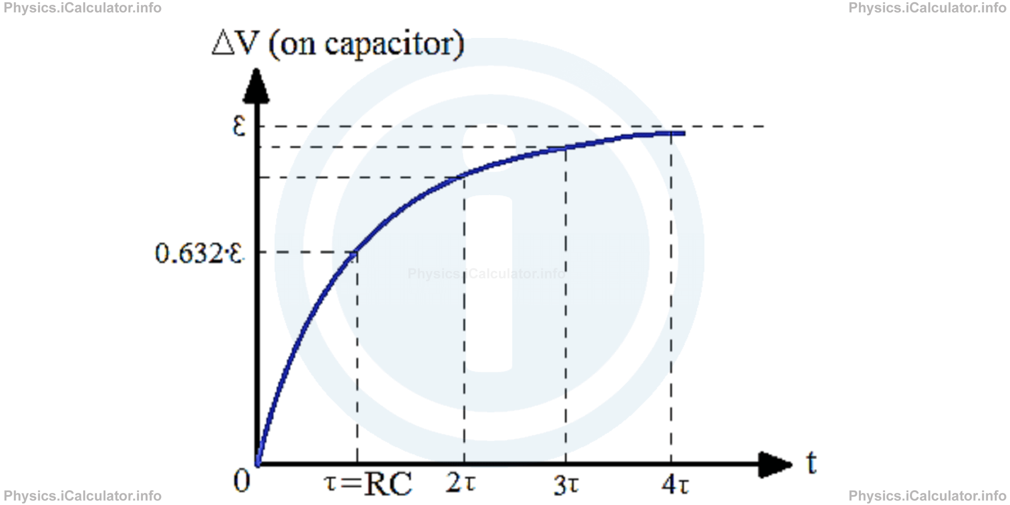
From the graph you can see that the capacitor is almost fully charged for t = 4τ = 4RC.
The value 0.632 ∙ ε for t = τ is found by doing the calculations, i.e.
= ε ∙ (1 - e-R ∙ C/R ∙ C )
= ε ∙ (1 - e-1 )
= ε ∙ (1 - 1/e)
Since the value of the Euler's Number e is approximately 2.718, we obtain
= ε ∙ (e - 1/e)
= ε ∙ (2.718 - 1/2.718)
= ε ∙ 1.718/2.718
= 0.632 ∙ ε
Properties of capacitors connected in RC circuits include:
- The charge on a capacitor connected in a RC circuit does not change instantaneously. This process takes some time. Since for small time intervals the current produced in the circuit is I = Q / t, the charge accumulated on the capacitor plates is very small for small time intervals because these two quantities are directly proportional to each other, that is Q = I ∙ t.
- The current flowing into a capacitor in the steady state reached after a long time interval is zero. Since charge builds up on a capacitor rather than flowing through it, charge can build up until the point that the potential difference ΔV=Q / C balances out the external voltage (electromotive force of the source) pushing charge onto the capacitor.
The discharge of a capacitor in a RC circuit is the inverse process of capacitor charging. Therefore, we obtain a decreasing exponential function when considering the potential difference vs time variation. The equation of potential difference of a capacitor during the discharge process is
Example 1
The switch of the circuit shown in the figure below has been for a long time in the position a.
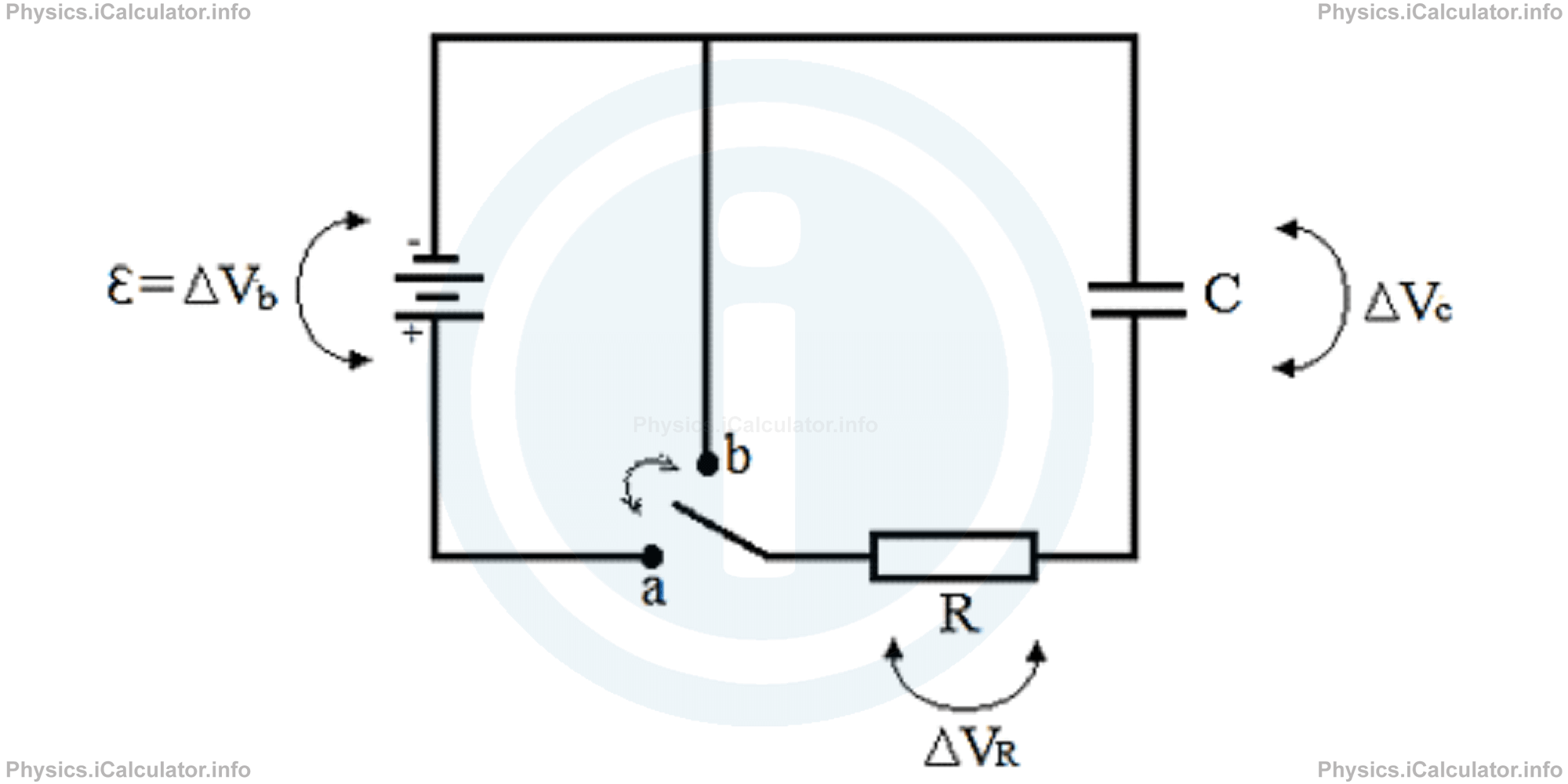
- What is the current through the resistor just before the switch is moved from a to b?
- What is the current flowing through the resistor after the switch is moved from position a to position b?
- What is the charge across the capacitor just before the switch is moved from position a to b?
- What is the charge on the capacitor immediately after the switch is moved from a to b?
- What is the potential difference across the capacitor at time t = 0.5 milliseconds after the switch is moved from position a to b?
- What is the charge stored in the capacitor at time t = 0.5 milliseconds after the switch is moved from position a to b?
Numerical applications: ε = 18V, C = 40 μF (4 × 10⁻⁵F), R = 50 Ω.
Solution 1
- The circuit is open (not working) at the position a as the gap between the capacitor pales prevent electrons from flowing. Therefore, no current is flowing through it, as current needs a continuous flow to exist. Thus, if we write the current at position a as I1 and that in the position b as I2, we have: I1=0
- The circuit is close (ON) when the switch is moved at the position b. In this case, the current flowing through the circuit (if neglecting the resistance of conductor) is I2 = ε/R
= 18 V/50 Ω
= 0.36 A - When the switch was at the initial position (position a), the negative charges were collected at the upper plate of capacitor (as it was connected to the negative terminal of battery) producing a charge of -Q. As a result, positive charges of the same magnitude were collected on the other (lower) plate of capacitor due to induction producing a charge + Q. Given that ΔVc = ε = 18 V (due to the nearly zero resistance of wire), the magnitude of this charge was Q = C ∙ ∆V
= 40 × 10-6 F ∙ 18V
= 720 × 10-6 C
= 7.2 × 10⁻⁴ C (or 720 μC) - The charge does not changes instantly, so even immediately after the switch is moved at the position b, the charge in the capacitor remains the same as before (720 μC) for a small instant. Then, it starts to decrease in a negative exponential rate.
- At t = 0.5 ms = 5 × 10 - 4 s, the potential difference between the plates of capacitor is ∆V(t) = ε ∙ e- t/R ∙ C
∆V(t) = 18 ∙ e-5 × 10⁻⁴/50 ∙ 4 × 10-5
= 18 ∙ e-1/4 V
= 18 ∙ e-0.25 V
= 18/4√e V
= 18/1.284 V
= 14 V - Since capacitance of a capacitor is calculated by the equation C = Q / ΔV and given that the capacitance here is constant (we have the same capacitor during the entire process), it is obvious that the expression which gives the amount charges stored in the capacitor as a function of time is similar to that of potential difference vs time discussed above, i.e. Q(t) = Q0where Q0 is the initial charge (here Q0 = 720 μC) and Q(t) is the charge in the capacitor at the instant t.
∙ e- t/R ∙ C
Therefore, the amount of charge stored in the capacitor at t = 0.5 ms, is
= 720 μC/1.284
= 561 μC
= 5.61 × 10⁻⁴ C
Remark! The RC circuits discussed in this tutorial are series RC circuits. There exist also parallel RC circuits the explanation of which need a complex analysis that goes beyond the scope of this tutorial.
You have reached the end of Physics lesson 15.7.2 Charging and Discharging a Capacitor. There are 2 lessons in this physics tutorial covering RC Circuits, you can access all the lessons from this tutorial below.
More RC Circuits Lessons and Learning Resources
Whats next?
Enjoy the "Charging and Discharging a Capacitor" physics lesson? People who liked the "RC Circuits lesson found the following resources useful:
- Capacitor Feedback. Helps other - Leave a rating for this capacitor (see below)
- Electrodynamics Physics tutorial: RC Circuits. Read the RC Circuits physics tutorial and build your physics knowledge of Electrodynamics
- Electrodynamics Revision Notes: RC Circuits. Print the notes so you can revise the key points covered in the physics tutorial for RC Circuits
- Electrodynamics Practice Questions: RC Circuits. Test and improve your knowledge of RC Circuits with example questins and answers
- Check your calculations for Electrodynamics questions with our excellent Electrodynamics calculators which contain full equations and calculations clearly displayed line by line. See the Electrodynamics Calculators by iCalculator™ below.
- Continuing learning electrodynamics - read our next physics tutorial: Miscellaneous
Help others Learning Physics just like you
Please provide a rating, it takes seconds and helps us to keep this resource free for all to use
We hope you found this Physics lesson "RC Circuits" useful. If you did it would be great if you could spare the time to rate this physics lesson (simply click on the number of stars that match your assessment of this physics learning aide) and/or share on social media, this helps us identify popular tutorials and calculators and expand our free learning resources to support our users around the world have free access to expand their knowledge of physics and other disciplines.
Electrodynamics Calculators by iCalculator™
- Amount Of Substance Obtained Through Electrolysis Calculator
- Charge Density Calculator
- Electric Charge Stored In A Rc Circuit Calculator
- Electric Field In Terms Of Gauss Law Calculator
- Electric Power And Efficiency Calculator
- Electron Drift Velocity Calculator
- Equivalent Resistance Calculator
- Force Produced By An Electric Source Calculator
- Joules Law Calculator
- Ohms Law Calculator
- Potential Difference In Rc Circuit Calculator
- Resistance Due To Temperature Calculator
- Resistance Of A Conducting Wire Calculator